background image

Safety and Compliance Information 

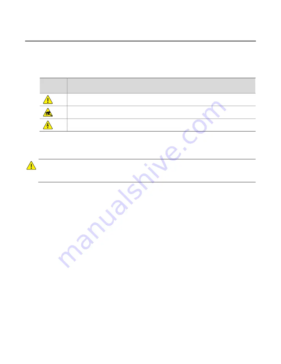
Conventions Used Symbol 

The symbols in this chapter are shown in the following table. They are used to remind the reader of the 
safety precautions during equipment installation and maintenance. 

Safety 

Symbol 

Description 


Generic alarm symbol: To suggest a general safety concern. 


ESD protection symbol: To suggest electrostatic-sensitive equipment. 


Electric shock symbol: To suggest a danger of high voltage.  


Safety Information 


WARNING! 

Installation  and  removal  of  the  unit  and  its  accessories  must  be  carried  out  by  qualified  personnel.  You 
must read all of the Safety Instructions supplied with your equipment before installation and operation. 


Warnings: 


If the product does not work properly, please contact your dealer or the nearest service center. (We 
shall not assume any responsibility for problems caused by unauthorized repair or maintenance.)  


To reduce the risk of fire or electrical shock, do not expose this product to rain or moisture.  


This  installation  should  be  made  by  a  qualified  service  person  and  should  conform  to  all  the  local 
codes.  


Please install blackouts equipment into the power supply circuit for convenient supply interruption.   


The separate earthing terminal must be permanently connected to earth. 


For AC supplied model: The plug-socket combination must be accessible at all times as it serves as the 
main disconnecting device. 


Before the power cable is installed or removed, the power must be turned off. 


To avoid heat accumulation, good ventilation is required for a proper operating environment.   


Improper  use  or  replacement  of  the  battery  may  result  in  hazard  of  explosion.  Please  use  the 
manufacturer recommended battery type. 

Summary of Contents for NVR200 series

Page 1: ...NVR200 300 500 Series Network Video Recorders User Manual Manual Version 100 20140730 Zhejiang Uniview Technologies Co Ltd...

Page 2: ...uration and servicing administrators Product users Precautions If this equipment is used in a domestic environment radio disturbance may arise When such trouble occurs you might be required to take co...

Page 3: ...our dealer or the nearest service center We shall not assume any responsibility for problems caused by unauthorized repair or maintenance To reduce the risk of fire or electrical shock do not expose t...

Page 4: ...frequency energy and if not installed and used in accordance with the instruction manual may cause harmful interference to radio communications Operation of this equipment in a residential area is li...

Page 5: ...ick Menu for Broadcast Group 12 3 Playback 13 Playback by Camera 13 Playback by Label 14 Playback by Local File 15 4 Camera Settings 15 Configuring Basic Information 15 Configuring Video and Audio Set...

Page 6: ...lient 46 Configuring Route 47 Configuring SMTP 48 Configuring DNS 49 10 NVR Management and Maintenance 50 Setting Your NVR 50 Setting Basic Information 50 Setting Date and Time 51 Setting the Language...

Page 7: ...ng a User 65 12 Client Computer Settings 65 13 Others 66 Configuring Encoder 66 Configuring Voice Resource 68 Configuring Serial Port 69 Configuring Virtual Channel 70 Configuring Video Output 72 Conf...

Page 8: ...gin page is displayed 2 Enter your username and password If this is the first time you log in to the Web interface for your NVR use admin as the username and password 3 Click Login The live view windo...

Page 9: ...ard Page 2 Click Browse to select a folder for ActiveX And click Next Figure 1 3 Select Installation Folder 3 Install ActiveX according to the guidance and click Finish to complete the installation Fi...

Page 10: ...configuration has completed for your camera For detailed information about initial configuration for a camera see the manual delivered with the camera Steps 1 Click Configuration Resource Configuratio...

Page 11: ...cription Access Protocol Protocol for connecting the camera to your NVR Uniview IPC ONVIF1 0 IPC ONVIF2 0 Note The parameters and processes of adding device may vary with the protocol you select Devic...

Page 12: ...ulticast group must be unique in the system Forward Mult Port 3 After you have completed the settings click OK Searching and Adding a Camera 1 Click the Search button The Search page is displayed Figu...

Page 13: ...d Party IPC Page Figure 1 9 Add IPC Page 4 Set the parameters For ONVIF protocol make sure that you enter the correct username and password in the Add third Party IPC Page 5 After you have completed t...

Page 14: ...the camera And you can also right click the camera and then choose Config in the resource tree 2 Edit the settings as required Some of the parameters are described in the table below 3 After you have...

Page 15: ...fline video lost Status of connected PTZ cameras The icons from left to right mean online offline video lost Root node of the resource tree Folder Alarm input Alarm output Table 2 3 Explanation of Ico...

Page 16: ...ore the previous scene mode including the layout of panes live video and group switching Turn off contrast on all panes Click this icon to disable dynamic contrast enhancement for all panes When you c...

Page 17: ...nation of Icons on the PTZ Control Panel Icon Function or Locks or releases the PTZ Note Only admin can gain the control of a locked PTZ Releases the PTZ Any user can control a PTZ when it is not lock...

Page 18: ...n stream Start Sub Stream to Pane Display the live view with the sub stream this item turns gray if the IPC does not support sub stream Playback Play back a recording View Monitiring Relation List the...

Page 19: ...unction is disabled Note the volumn control is global for all voice resources which means when you adjust the volumn of one voice resouce the volumn of other resources changes accordingly Config Edit...

Page 20: ...n the live view window Steps 1 In the live view window click the Resource tree to expand it till you find the desired camera and then right click it The right click menu is displayed as shown in Figur...

Page 21: ...efore you use this function ensure that at least one label has been added for the recording you want to play back To add labels you can click in the Playback Control Panel when a recording is being pl...

Page 22: ...log box appears prompting you to select the file 2 Select the file and then click Open 4 Camera Settings Camera settings including basic settings settings for video and audio image On Screen Display O...

Page 23: ...e when network performance is degraded Clock Synchronization Enables disables clock synchronization with your NVR Multicast Enables disables multicast Make sure that the camera supports this function...

Page 24: ...o settings for your camera on the Video and Audio tab pages as required Prerequisite For an IPC that does not support this function the Video and Audio tabs are masked Depending on the model and type...

Page 25: ...eed two video streams from your camera one primary and one secondary Bit Rate Type CBR Constant Bit Rate which means the camera transmits data at a constant bit rate This mode is recommended when the...

Page 26: ...eters area shows the current settings The following shows an example Figure 4 5 Image Parameters 3 Modify the settings while watching the live video in the Live View area on the left 4 After you have...

Page 27: ...and size 7 To add more OSDs repeat steps 3 through 6 8 After you have completed the settings click OK Configuring Motion Detection Purpose Use this function to set an area on video from a camera so th...

Page 28: ...e object by entering a number in the text box or resizing the object in the Live Preview area using your mouse 8 Configure the Duration parameter to set the maximum duration of movement before an alar...

Page 29: ...area on the left and then drag the mask area to the right position 7 After you have completed the settings click OK Configuring ROI Purpose Use this function to set a region of interest ROI and ensur...

Page 30: ...rt check that the PTZ is properly connected to your NVR on the network Adding Preset Positions Purpose You need to add preset positions also called presets before you can add a patrol route Steps 1 In...

Page 31: ...control panel 8 Optional To delete an unneeded preset position select the preset position from the Preset drop down list and then click Creating a Patrol Route Purpose A patrol route consists of a cer...

Page 32: ...ton To adjust the sequence of the preset positions use the Set Top Move Up Move Down Set Bottom buttons 5 In the Time Interval text box enter a number to set the duration that the PTZ camera stays at...

Page 33: ...you want to set a patrol plan must have been created For detailed steps to create a patrol route see Creating a Patrol Route Steps 1 Click Configuration Service Configuration Patrol The Patrol page i...

Page 34: ...ute click View Modify Figure 4 18 Example Patrol Plan 6 Optional To set an exception to the current plan select Enable Exception and then set the exceptional period s or patrol route s 7 After you hav...

Page 35: ...e recordings for the connected cameras You need to build an array first and then make a storage plan Building an Array Purpose Build an array of disks to store recordings on your NVR Steps 1 Click Con...

Page 36: ...ots for the array 4 After you have completed all the settings click the Build Array button The new array is displayed in the array list The following shows an example Figure 5 3 Newly Built Array 5 Cl...

Page 37: ...ackup disk has the same capacity as the active disk When a hard disk of a RAID1 or RAID5 array is damaged Degrade is displayed in the Status column In this case you need to rebuild the array and repla...

Page 38: ...apacity Extended disk size to be used for storage Data Cover Mode Indicates the policy to be used when the assigned space is used up Overwrite On Full With this option selected data will be overwritte...

Page 39: ...plan must be created first For the steps to create a storage plan see Making a Storage Plan A storage plan is immediately effective once created If a storage plan is stopped you can follow these step...

Page 40: ...when an alarm is raised for the camera Configuring alarm triggered recording is the same as configuring alarm triggered storage For steps to configure alarm triggered storage see Configuring Alarm Tri...

Page 41: ...rameter must be consistent with the status of the alarm input device For example if the alarm input device is normally in open status you must set this parameter to Normal Open Boolean Indicates wheth...

Page 42: ...preset triggered live video to a specified pane triggered Boolean output and triggered buzzer The detailed steps are described in the following sections Configuring Alarm Triggered Storage Purpose The...

Page 43: ...displayed Figure 7 4 Alarm Triggered Action Configuration Page 3 In the Operation column of the Camera List area click Add for the camera for which you want to configure alarm triggered storage The c...

Page 44: ...TZ camera this camera will move to the preset position when an alarm is raised Steps 1 Click Configuration Service Configuration Alarm Alarm Triggering The Alarm Triggered Action Configuration page is...

Page 45: ...alarm is raised and meanwhile the border of the pane will turn red to alert you Steps 1 Click Configuration Service Configuration Alarm Alarm Triggering The Alarm Triggered Action Configuration page...

Page 46: ...ion List 4 Select the check box for camera 206 5 0 2 Figure 7 10 Select Camera 5 In the Users List double click the field in the Pane ID column and then select a pane for example pane No 3 and then cl...

Page 47: ...urpose of setting an output Boolean is to enable the NVR to report alarms to some extended devices and trigger actions caused by an alarm This section takes alarm source 20660185In1 as an example and...

Page 48: ...ick the pop up Input Boolean Alarm Action Figure 7 14 Configure Output Boolean Page 3 On the Alarm Triggered Action Configuration page click the Output Boolean tab In the Boolean List find an availabl...

Page 49: ...r tab Figure 7 16 Buzzer Tab 3 Select YES to enable this function and then click OK Configuring Alarm Triggered Email Purpose Use this function so that the NVR device will be triggered to send an emai...

Page 50: ...click start or stop as required 9 Network Settings Some network settings must be configured before your NVR can operate on the network depending on the configuration of your NVR For detailed descript...

Page 51: ...R Use the following IP address Select this option if you want to set a static IP address subnet mask and gateway IP Address IP address of your NVR Subnet Mask Subnet mask of the network Gateway IP add...

Page 52: ...tings click OK Configuring NAT Purpose NAT means Network Address Translation NAT When this function is enabled for your NVR the private IP address and port number of your NVR will be translated into a...

Page 53: ...ed 4 Click OK to save the settings Configuring UNP Client Purpose Set the Universal Network Passport UNP client so that your NVR can communicate with the UNP server Before configuring an IP address fo...

Page 54: ...Username and password of the UNP server Note you can ignore the username and password if the authentication function is disabled Password 3 After you have completed the settings click OK Configuring R...

Page 55: ...Purpose The NVR can be set to send an alert email to specified users when an alarm is raised Before you start configuring SMTP ensure that your NVR is connected to the LAN where the SMTP server is loc...

Page 56: ...uthentication is required If authentication is enabled you need to set the username and password for authentication Sender Name Name of the sender to be shown to the email receipt s Sender Address Add...

Page 57: ...Click OK 10 NVR Management and Maintenance Setting Your NVR Set parameters for your NVR including basic information date and time and language Setting Basic Information Purpose Set the basic informati...

Page 58: ...pses before a PTZ is released automatically when the user controlling the PTZ does not perform any operation and no other user is gaining control of the PTZ from the current user during this period 6...

Page 59: ...address When the settings are completed the time on your NVR will be synchronized with the NTP server The following shows an example Figure 10 3 Setting the Date and Time with NTP Enabled 4 Set the c...

Page 60: ...iew information about operation status of your NVR including the current system time length of time that the system has been operating CPU usage information RAM information etc Steps 1 Click Maintenan...

Page 61: ...esh to get the latest status information Viewing Service Statistics Purpose View service statistics of your NVR such as the number of live video services established number of two way voice sessions a...

Page 62: ...ver Steps 1 Click Maintenance Running Status Server Information The Server Information page is displayed If your NVR is operating in stand alone mode the Management Mode indicates stand alone mode Vie...

Page 63: ...tory Alarms Purpose View history alarms including alarm name involved devices alarm level time when the alarm is raised and current alarm status Steps 1 Click Maintenance Alarm Query Instant Alarm The...

Page 64: ...onfiguration file You can also import configuration file to save the trouble of manually configuring the device repeatedly Steps 1 Click Maintenance Device Maintenance Export Import The Export Import...

Page 65: ...information about events that have occurred in the system Steps 1 Click Maintenance Log Query Operation Log The Operation Log page is displayed Figure 10 13 Operation Log Page 2 Select the desired it...

Page 66: ...Maintenance Export Log The Operation Log page is displayed Figure 10 16 Export Log Page 2 Click Export A dialog box appears 3 Select the destination folder for the logs to be exported and then click O...

Page 67: ...e is displayed Figure 10 18 Shutdown Page 2 Click Shut Down A message appears for your confirmation 3 Click YES to proceed or click NO to cancel the operation Upgrading Your NVR Purpose Upgrade your N...

Page 68: ...rough the man machine interface and the Web interface at the same time For example a man machine interface administrator can gain control of a resource from a Web interface operator because an adminis...

Page 69: ...g Box 3 Enter the user information including user ID username role and password For example enter 001 as the user ID and username select Operator as the role Enter other information as required Figure...

Page 70: ...ideo Playback 7 In the Global Authentication area select the permissions you want to assign to the user for example Storage Configuration Alarm Configuration Alarm Process and Log Query Table 11 1 Glo...

Page 71: ...unctions such as 2 way audio and broadcast Log Query This parameter sets whether the user can query logs If this option is not selected the Maintenance Log Query is not displayed for the user 8 After...

Page 72: ...ppears click YES to confirm the lock operation The icon changes to in the User Status column which means that the user is locked 3 To unlock the user click Unlock in the Lock Unlock column and then cl...

Page 73: ...Description Smart Stream Enable disable the auto switch between main stream and sub stream Default Live Video Stream Choose the default video stream used for live view when IPC is connected to NVR Li...

Page 74: ...C Steps 1 Click Configuration Resource Configuration Encoder The Encoder page is displayed Figure 13 1 Encoder Page 2 Click Add and the Add Encoder dialog box is displayed Configure the parameters as...

Page 75: ...rce page is displayed On the Talk Broadcast tab the available voice resources are listed On the Broadcast Group tab you can add broadcast groups Figure 13 3 Voice Resource Page 2 On the Talk Broadcast...

Page 76: ...ources Configuring Serial Port Purpose Before using a serial port to control an extended device or to maintain the NVR you must configure serial port parameters Steps 1 Click Configuration Resource co...

Page 77: ...t whose port type is RS485 RJ45 and set transparent channel parameters in the Serial Port Configuration dialog box Figure 13 7 Serial Port Configuration Dialog Box Figure 13 8 Serial Port Configuratio...

Page 78: ...ion Resource Configuration Virtual Channel The Virtual Channel page is displayed In the status column click the icon to enable the virtual channel Figure 13 9 Virtual Channel Page 2 On the Virtual Cam...

Page 79: ...ured vary with the device model By editing the corresponding video output interfaces you can configure the display of virtual channel For details about configuring virtual channel see Configuring Virt...

Page 80: ...e setting the transparent channel parameters For details about setting a serial port see Configuring Serial Port Steps 1 Click Configuration Service Configuration Transparent Channel The Transparent C...

Page 81: ...ssage appears to prompt you to download ActiveX check your IE settings at Tools Internet options Browsing history and then select Every time I visit the webpage for Check for newer versions of stored...

Page 82: ...nd PTZ address and make sure that are set properly Some IPCs cannot be connected to the NVR through ONVIF How to handle this Answer 1 Check that the IPC settings including IP port number username and...

Page 83: ...http www uniview com en globalsupport uniview com...

Reviews: