background image

ZGR SCALABLE 60 

– 300 KVA 


Manual de operaciones 

www.zigor.com 


5.4


Connection of Power Cables ..................................................................................................................... 48


Recommended cross-sectional areas for power cables ....................................................................... 49


Power cable connector requirements .................................................................................................... 50


Recommended input front-end and output back-end circuit breakers ................................................. 51


5.5


Power cable connection ............................................................................................................................. 51


5.6


Battery connection ..................................................................................................................................... 53


5.7


Online UPS Modules Replacement ............................................................................................................ 54


5.8


UPS parallel Installation ............................................................................................................................. 55


Cabinet installation ................................................................................................................................. 55


Parallel cable installation ........................................................................................................................ 55


LBS installation (Load Bus Synchronisation) ......................................................................................... 56


5.9


Comunication ............................................................................................... ¡Error! Marcador no definido.


CAN communication port definition ....................................................................................................... 58


Definición del puerto de comunicación RS485 ...................................................................................... 58


BAT_T communication port definition .................................................................................................... 59


REPO instruction .................................................................................................................................... 59


6


OPTIONS ............................................................................................................................................................. 61


6.1


SNMP card ................................................................................................................................................. 61


7


TROUBLESHOOTING ......................................................................................................................................... 62


7.1


Problems and Solution ZGR SCALABLE 60   300 KVA ............................................................................ 62


7.2


Recommended spare parts ........................................................................................................................ 63


8


MAINTENANCE ................................................................................................................................................... 64


8.1


Battery maintenance .................................................................................................................................. 65


9


TECHNICAL SPECIFICATIONS .......................................................................................................................... 66


10


STANDARDS ....................................................................................................................................................... 68


11


WARRANTY ........................................................................................................................................................ 69


© 2020, ZIGOR 

Reservados  todos  los  derechos.  No  está  permitida  la  reproducción  total  o  parcial  de  este  Manual  de  Operación,  ni  su 
transmisión  de  ninguna  forma  o  por  cualquier  medio,  ya  sea  electrónico  o  mecánico,  por  fotocopia,  registro  u  otro 
procedimiento de almacenamiento o recuperación de información sin permiso del editor. 

El contenido de este manual es exacto en el momento en que se procede a su impresión. Pero, con la intención de cumplir 
con el compromiso de una política de continuos desarrollos y mejoras, el fabricante se reserva el derecho de cambiar las 
especificaciones del producto, su funcionamiento, o los contenidos del Manual de Operación sin previo aviso. 

Summary of Contents for SCALABLE 60 KVA

Page 1: ...Operation Manual ZGR SCALABLE 60 300 KVA Online Three phase UPS www zigor com...

Page 2: ......

Page 3: ...odes 13 Normal mode 13 Battery mode Stored Energy Mode 13 Bypass mode 14 ECO Mode 14 Maintenance mode Manual Bypass 15 3 2 Turn on off UPS 15 Restart procedure 15 Test procedure 16 Maintenance bypass...

Page 4: ...SNMP card 61 7 TROUBLESHOOTING 62 7 1 Problems and Solution ZGR SCALABLE 60 300 KVA 62 7 2 Recommended spare parts 63 8 MAINTENANCE 64 8 1 Battery maintenance 65 9 TECHNICAL SPECIFICATIONS 66 10 STAND...

Page 5: ...designed is defined in the documentation The system shall be exposed only to admissible environmental conditions These are defined in the technical details provided for the equipment ZIGOR accepts no...

Page 6: ...water For the sake of human being safety please well earth the UPS before starting it Do not throw batteries into a fire as they may explode The standard UPS output with internal batteries can be powe...

Page 7: ...l and reuse of waste from EEE To dispose of this product and ensure its proper management follow the current local environmental legislation and regulations In this way it will contribute to conserve...

Page 8: ...s label placed at the rear or on one side of the unit Responsibility for the loss or damage of Products shall transfer to the Customer from the moment ZIGOR places these at his disposal in the place...

Page 9: ...he UPS can solve most of the power supply problems such as blackout over voltage under voltage voltage sudden drop oscillating of decreasing extent high voltage pulse voltage fluctuation surge inrush...

Page 10: ...view of ZGR SCALABLE 30 60 kVA Fig 2 3 Rear view of ZGR SCALABLE 30 60 kVA Fig 2 4 Front view of ZGR SCALABLE 30 60 kVA redundant power module and bypass module are optional Fig 2 5 Front view of ZGR...

Page 11: ...GR SCALABLE 90 300 kVA Fig 2 9 Rear view of ZGR SCALABLE 90 300 kVA Fig 2 10 Front view of ZGR SCALABLE 90 270 kVA Redundant power module and bypass module are optional Fig 2 11 Front view of ZGR SCAL...

Page 12: ...n mains bypass separation 15 Bypass C input copper bar Wiring must be used when mains bypass separation 16 Input neutral copper bar 17 Output neutral copper bar 18 Ground copper bar 19 Battery positiv...

Page 13: ...rt NC 12V normally close port 2 SWITCH STATUS OUT 0V output breaker auxiliary contact signal port MT 0V maintenance breaker auxiliary contact signal port BP 0V bypass breaker auxiliary contact signal...

Page 14: ...for software update and history download 4 RS232 port for communication 5 LCD port 6 CAN port BMS port 7 FE Net port reserve 8 RS485 port for communication 9 RS485 port for communication 10 BAT_T bat...

Page 15: ...ns and supplies DC power to the inverter while floating and boosting charge the battery simultaneously Then the inverter converts the DC power to AC and supplies the load Fig 3 1 Fig 3 1 Normal mode B...

Page 16: ...load This is to avoid paralleling of unsynchronized AC sources This interruption is programmable but typically set to be less than an electrical cycle e g less than 15 ms 50 Hz or less than 13 33 ms 6...

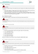
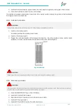
Page 17: ...module_in switch at the on status 4 When AC MAINS input voltage within the range and the rectifiers of the UPS will be started up in 30 up 5 Switch ON output switch If the rectifier of the module doe...

Page 18: ...RY breaker 4 Switch OFF MAINS breaker 5 Switch OFF BYPASS breaker 6 Switch OFF OUTPUT breaker At this time the bypass source will supply to the load through the MAINTENANCE breaker 3 2 3 2 Switch to n...

Page 19: ...g 3 6 When battery normal rectifier starts operation 30 s later inverter starts and operates and the green LED will light on Fig 3 6 Cold Start Shut down procedure 1 Press the INVERTER OFF key on the...

Page 20: ...single mode is changed to parallel mode set the parallel number for each UPS up to 6 units can be parallel set the ID of each cabinet the ID of each unit must be different 5 Switch ON the input switch...

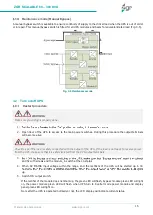
Page 21: ...control panel areas and elements Click the main block to enter the main data display window click return to return to the previous window click home page to return to the main page Datas menu This men...

Page 22: ...ttery Fig 4 4 Moreover it can also be entered through by real time data block the status of the switches dry contacts through clicking on the block enter the corresponding data window Fig 4 4 Status m...

Page 23: ...submenu Click the bypass block to enter the bypass data display window Fig 4 6 Fig 4 6 Status Bypass submenu 4 1 2 3 Output submenu Click the output block to enter the output data display window Fig 4...

Page 24: ...enter the battery data display window Fig 4 9 y Fig 4 10 Fig 4 9 Status Battery 1 submenu Fig 4 10 Status Battery 2 submenu 4 1 2 5 Status info submenu To access to the status information click the b...

Page 25: ...o 2 submenu Fig 4 13 Status Status Info 3 submenu 4 1 2 6 Module submenu Click the module block to enter the module data display window Fig 4 14 Fig 4 14 Status Module submenu Alarm menu It allows vie...

Page 26: ...5 Alarm menu 4 1 3 1 Curr Alarm submenu Click the curr alarm to enter the current alarm display window Fig 4 16 Fig 4 16 Alarm Curr Alarm submenu 4 1 3 2 History submenu Click the history to enter the...

Page 27: ...the buzzer is on then click the block buzzer will on and the block will change to green Fig 4 19 Fig 4 18 Alarm Buzzer on submenu Fig 4 19 Alarm Buzzer mute submenu Setting menu There are two levels t...

Page 28: ...gor com 26 4 1 4 1 Basic Setting submenu Click basic setting Fig 4 23 and enter by input the correct password Fig 4 21 and Fig 4 22 The user password is 111111 Fig 4 21 Password window Fig 4 22 Passwo...

Page 29: ...re login when the setting value is set click left or right block to change the value Fig 4 25 Settings Basic Settings Password submenu Brightness and backlight time submenu Click the block to change...

Page 30: ...figuration block to save Fig 4 27 o Date Format has 3 formats o Date current date o Time current time Fig 4 27 Settings Basic Settings Date and Time submenu Communication setting submenu Click the tex...

Page 31: ...ck the text to select other value or input new value and click save configuration block to save Fig 4 30 to Fig 4 46 o Working Mode Seleccione el modo de trabajo del SAI Single Mode modo nico Parallel...

Page 32: ...gle and short distance Rs485 for multiple and far distance Fig 4 31 Settings Advanced Settings System Setting 2 submenu o Power Walk in this is enable the UPS to control the interval that each module...

Page 33: ...ue some power module will turn to inverter mode after setting the sleep mode enable Default value is disable Fig 4 33 Settings Advanced Settings System Setting 4 submenu o Paralallel ID Parallel opera...

Page 34: ...value can be 5 0 5 step is 0 5 default value 0 Fig 4 35 Settings Advanced Settings System Setting 5 submenu o Battery Group Must modify the number to actual configuration The value can be 1 8 default...

Page 35: ...be 2 30 2 40 V cell and is 2 30 V cell by default o Aver charging Duration boost charge time limit the value can be 1 999min and is 240 by default Fig 4 37 Settings Advanced Settings System Setting 7...

Page 36: ...Limit When the difference between the bypass voltage and the rated voltage exceeds the lower threshold for the bypass voltage the system determines that the bypass voltage is abnormal and that the byp...

Page 37: ...urs The default value is Enable o Bypass Switches Limit Cross currents occur during the transfer between bypass mode and normal mode which impacts the system This parameter specifies the number of tra...

Page 38: ...connection detection The default value is Disable o BYP Switch Enable or disable bypass breaker connection detection The default value is Disable o BATT Ground Fault Enable or disable battery groundi...

Page 39: ...n set to normally closed or normally opened The default value is normally opened Setting value No ITEM No ITEM 1 URGENT_ALARM 7 BYPASS_SUPPLY 2 MINOR_ALARM 8 BATTERY_SUPPLY 3 MAIN ABNORMAL 9 NO_SUPPLY...

Page 40: ...4 submenu Maint menu In this menu the History can be downloaded the touch correction adjusted and done a battery self test Fig 4 47 Fig 4 47 Maint menu 4 1 5 1 USB Wizard submenu This submenu provides...

Page 41: ...SB Wizard Alarm log output submenu Setting log output submenu Fig 4 50 Fig 4 50 Maint USB Wizard Setting log output submenu 4 1 5 2 Battery Self Check submenu It can be selected the check by Timing Da...

Page 42: ...4 52 Fig 4 52 Maint Battery Self Check Timing daily submenu Timing weekly Modify the check date time and check time 10S default 10min EOD Fig 4 53 Fig 4 53 Maint Autocomprobaci n de la bater a Timing...

Page 43: ...ter can be started up or switched off INV ON OFF depending on the configuration Fig 4 56 Single OFF Inverter OFF location UPS Single ON Inverter ON location UPS Parallel OFF Inverter OFF all parallel...

Page 44: ...42 Fig 4 57 Common Battery Test submenu 4 1 6 3 Fault Clear submenu Clear the current fault not for all faults Fig 4 58 Fig 4 58 Common Fault Clear submenu About Menu It shows the software version Mo...

Page 45: ...econd Fault LED lit 2 003 REC par cable Fault Twice per second Fault LED lit 3 004 REC Over Current Beep continuously Fault LED lit 4 005 REC Power Fault Beep continuously Fault LED lit 5 007 Input SC...

Page 46: ...mode Fault Beep continuously Fault LED lit 33 06B Fuse Broken Beep continuously Fault LED lit 34 081 Par cable Fault Twice per second Fault LED lit 35 086 ECU Insert Fault Once per 2 seconds Fault LED...

Page 47: ...conds Alarm LED lit 13 10F Set Data Err Once per 2 seconds Alarm LED lit 14 121 INV Par cable abnormal Once per 2 seconds Alarm LED lit 15 125 INV Overload Once per 2 seconds Alarm LED lit 16 126 INV...

Page 48: ...nce per second Alarm LED lit 33 164 Once per second Alarm LED lit 34 151 Ecu Set Data Err Once per 2 seconds Alarm LED lit 35 161 BPS Par cable abnormal Once per 2 seconds Alarm LED lit 36 165 Bypass...

Page 49: ...re can t be higher than 50 If the UPS is dismantled under low temperature it might be in a condensing condition The UPS can t be installed unless the internal and external of the equipment is fully dr...

Page 50: ...rnal Battery The UPS and its associated batteries are protected against the effect of over current through a DC compatible thermo magnetic circuit breaker or a set of fuses located close to the batter...

Page 51: ...ditions such as cable layout or ambient temperatures change perform verification in accordance with the IEC 60364 5 52 or local regulations If the rated voltage is 400 V multiply the currents by 0 95...

Page 52: ...cables no longer than 50 m Power cable connector requirements UPS CABINET KVA CONNECTOR CONNECTION MODE BOLT TYPE BOLT HOLE DIAMETER TORQUE 30 50 45 60 50 100 75 125 120 150 1 2 m Mains input connect...

Page 53: ...P 250A 3P 400A 3P 135 150 250A 3P 250A 3P 250A 4P 250A 3P 500A 3P 180 200 225 400A 3P 400A 3P 400A 4P 400A 3P 630A 3P 250 270 500A 3P 500A 3P 500A 4P 500A 3P 800A 3P 300 600A 3P 600A 3P 600A 4P 600A 3...

Page 54: ...ower cable Refer to the table above and pay attention to the diameter of the connection terminal of the cable that should be greater than or equal to that of the connection poles Fig 5 3 Connection of...

Page 55: ...er can choose the capacity and the numbers of the batteries according to their desire Fig 5 4 Fig 5 4 External battery connections for long run units WARNING If the load equipment is not ready to acce...

Page 56: ...e module is inserted properly then the indicator will flash 3 Fix the module with screws 1 at the positioning screw holes 4 Switch on the module_ON switch 3 at the left of the module panel then the re...

Page 57: ...de The basic installation procedure of a parallel system comprising of two or more UPS modules is the same as that of single module system The following sections introduce the installation procedures...

Page 58: ...module to keep the outputs of two completely independent UPSs synchronized even if they come from two different power supplies LBS system contains LCD set cable connect and STS device 5 8 3 1 LCD set...

Page 59: ...GR SCALABLE 60 300 KVA Manual de operaciones www zigor com 57 Fig 5 8 LBS cable installation 5 8 3 3 UPS installation The whole systems are showed below Fig 5 9 Fig 5 9 Installation of the whole syste...

Page 60: ...3 7 CAN_GND Table 5 5 CAN Connection Available functions of CAN Communicate to BMS Communicate to remote LCD Definici n del puerto de comunicaci n RS485 Definition of port Fig 5 11 Fig 5 11 RS485 port...

Page 61: ...rt Fig 5 12 Fig 5 12 BAT_T port Table 5 7 DEVICE RJ45 UPS RJ45 DESCRIPCTION Pin 1 5 Pin 1 5 485 A Pin 2 4 Pin 2 4 485 B Pin 7 Pin 7 12 Vdc Pin 8 Pin 8 GND Table 5 7 BAT_T Connection Available function...

Page 62: ...n and UPS REPO port Table 5 8 BUTTON UPS REPO DESCRIPTION Pin 1 Pin 1 EPO NA Pin 2 Pin 2 EPO 12 V Pin 1 Pin 3 EPO NC Pin 2 Pin 4 EPO 12 V Table 5 8 REPO Connection A remote emergency stop switch can b...

Page 63: ...ts supports the Modem Dial in PPP function to enable the remote control via the internet when the network is unavailable In addition to the features of a standard NetAgent Mini NetAgent II has the opt...

Page 64: ...LED does not light on and the UPS operates at battery mode The input switch of the Modules are not switched on input cable is not well connected Switch on the input switch Make sure the input cable is...

Page 65: ...e UPS 14 Cannot Black start Battery switch is not properly closed Battery fuse is not open Or Battery low Close the battery switch Change the fuse Recharge the battery 15 Buzzer beeps continuously and...

Page 66: ...side panel and the case bottom 6 monthly o Check on the correct ventilation of the location o Cleaning of the equipment s air inlet filters o Removal of foreign bodies both in the air inlet and outle...

Page 67: ...charge charge cycles it will be shortened if temperature raised or deep discharged Periodical maintenance is required so as to keep battery in good condition 1 The most proper working temperature is 1...

Page 68: ...k 300k Module 15 kVA 15k Max Number 3 5 4 10 9 CABINET 10 KVA MODULE 30 KVA 50 KVA 100 KVA Capacity UPS cabinet 10 30 kVA 10 30 kW 10 50 kVA 10 50 kW 10 100 kVA 10 100 kW Module 10 kVA 10k Max Number...

Page 69: ...ns Short circuit overload overtemperature battery low fan fault Transfer time Utility to Battery 0 ms Utility to bypass 0 ms Overload Line Mode 110 overload for 60 min 125 overload for 10 min 150 over...

Page 70: ...00 KVA model described in this manual comply with the following European regulations I European electromagnetic compatibility directive EMC Standard EN 62040 1 2008 A1 2013 IEC EN 62040 3 2011 II Unin...

Page 71: ...ating annual referring to the Installation Conditions When the customer not clearly proves the systematic realization of regular maintenance operations described in the Operating Manual Equipment dete...

Page 72: ...zigor com Consulte nuestra web para contactar con la red de delegaciones comerciales Refer to our website in order to contact the commercial branches network Veuillez consulter notre page web pour con...

Reviews: