Initial
Installation
EN 4161.758.101m – 2018-09
21
4.3.6
Gearbox – fit
The M8 set screw (9) (see Fig. on page 16, 17,
19) must be screwed in and tightened at the
parallel key with 18 Nm until firmly home. Make
sure you coat the threaded pin with liquid seal
before installing it.
Make sure that the O-ring (10) is in the correct
position during installation (see Fig. on page 16,
17, 18, 19). The O-ring is delivered loose with the
gearbox and has to be coated with grease before
being inserted into the seal groove in the housing.
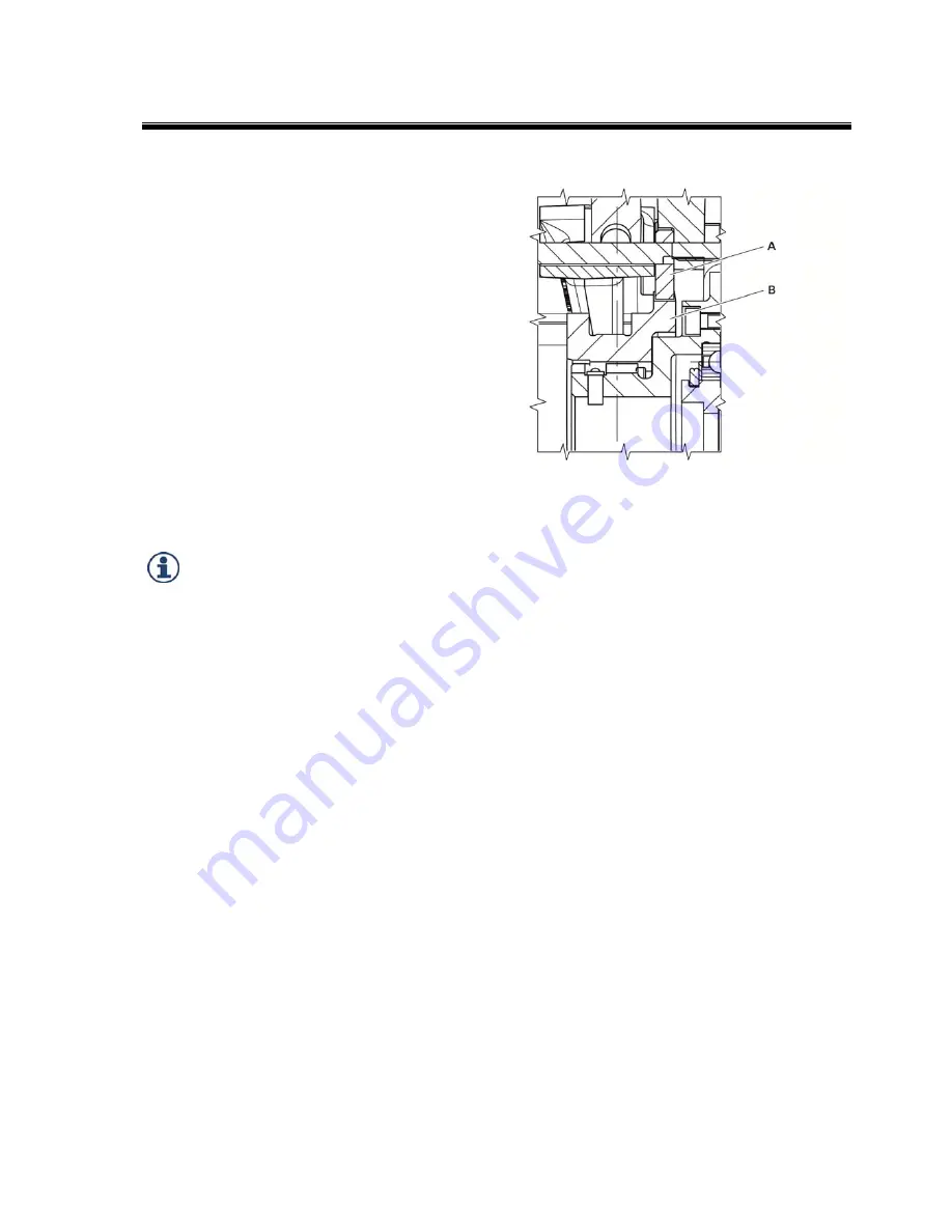
Check the position of the gearbox shift
mechanism. The sliding sleeve must be in the 1
st
gear position (“low” gear ratio).
Take up the gearbox and place it onto the motor
flange. Carefully bring the sun gear/hub
connection together when doing this.
The external spline of the sun gear must be
guided into the internal spline of the hub.
This can be made easier by turning to the left or
right at the gearbox output
.
The gearbox housing, adapter plate and motor are
bolted together using four or eight hexagon bolts
(11) (see Fig. on page 16, 17, 18, 19).
Fill the gearbox with oil and connect up the
recirculating lubrication system and the power
supply. The breather outlet must always be at the
top, regardless of the installation position. The
breather is screwed in to position B5 ex works.
The gearbox is now ready for use.
The gearboxes can be operated under the same
degrees of protection as those defined for AC
and DC motors.
When setting up, make sure that the motor
cooling air can flow in and out unhindered.
Before taking the electric motor/gearbox assembly
into operation, check that the gearbox output can
be turned by hand.
In the case of drive units that are fixed on the
gearbox flange or housing, the motor can be
supported on the B-side so that it does not vibrate.
1
st
gear position:
A Brake disk
B Sliding sleeve


