


Initial Installation
20
EN 4161.758.101m – 2018-09
4.3.5
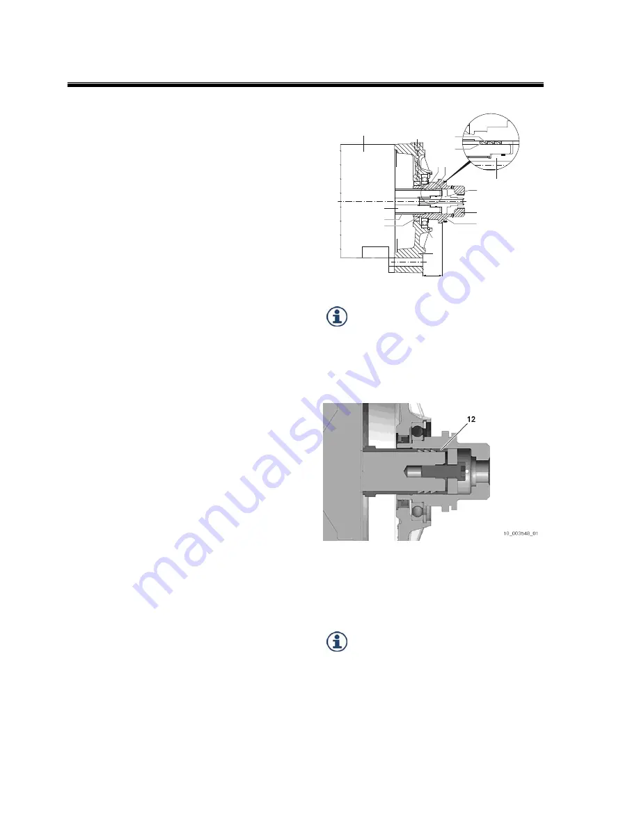
Closed design with hub bearing,
shaft seal and keyless hub
When mounting on motors with a smooth motor
shaft without a keyway, it is necessary to use ring
clamping elements and pressure pieces between
the motor shaft and the input hub in order to
transmit the torque. There must be a central
thread in the motor output shaft.
The mating surfaces of the motor (3), motor shaft
(2) and input hub (1) must be cleaned.
Check the motor shaft (2) for axial and radial
runout as described in chapter 4.1.
Loosely mount the counter-holder (4), ring
clamping elements (5+6), bush (12), pressure
piece (7) and screw connection with thread lock
(8) in advance. Watch out for the position of the
ring clamping elements when doing this.
First
install the inner
(5)
then the outer
(6)
ring
clamping elements
in the pack on the motor
shaft.
Push the input hub onto the motor shaft with or
without adapter plate (9), depending on the
version.
By hand, move the ring clamping elements into
contact using the screw connection. Tightening
the screw connection causes the hub (and the
adapter plate, if fitted) to move axially towards the
motor. Take this into consideration with a lead
dimension of +0.4 mm.
Tighten screw connection (8) to 90 Nm for M12.
Take note of the maximum torque permitted for
the thread in the motor shaft. Screws with a
strength category of 10.9 must be used with
adaptations without a coolant flow.
Check dimension C and the concentricity of the
hub.
There is no longer any need for an additional
internal seal in conjunction with ring clamping
elements. The number of ring clamping elements
and bushes can vary depending on the motor.
In screw connections with a hole for the coolant to
flow through, watch out for the O-rings and grease
them before installation.
The input hub must be blocked in order to prevent
twisting of the motor shaft and input hub when
tightening. This can be done using a special tool
ZF 1X46.190.227.
DO NOT GREASE
the motor shaft (2) and
the hole in the input hub (1).
Lightly oil
the cone surface of the ring
clamping elements (5+6).
The counter-holder is supported on the shoulder of
the motor shaft. It is necessary to have a large
contact surface.
In the closed version without hub bearing, grease
the seal running surface for the radial oil seal on
the input hub before installation. Watch out for the
position of the sealing lip when pushing on the
input hub.
When using the enclosed design with hub
bearing (10) and radial oil seal (11), do not
push the input hub onto the motor shaft
using the adapter plate. Once the screw
connection has been tightened, the adapter
plate must be in contact with the motor
housing and it must be possible to turn it
freely. This means the hub bearing is free
from tension.
3
6
5
5 6
8
8
1
7
10
9
C
11
4
2


