


USERS GUIDE
NR2310D-ROG
REVISION
N
DATE
031121
Page #:
1
www.novuspower.com
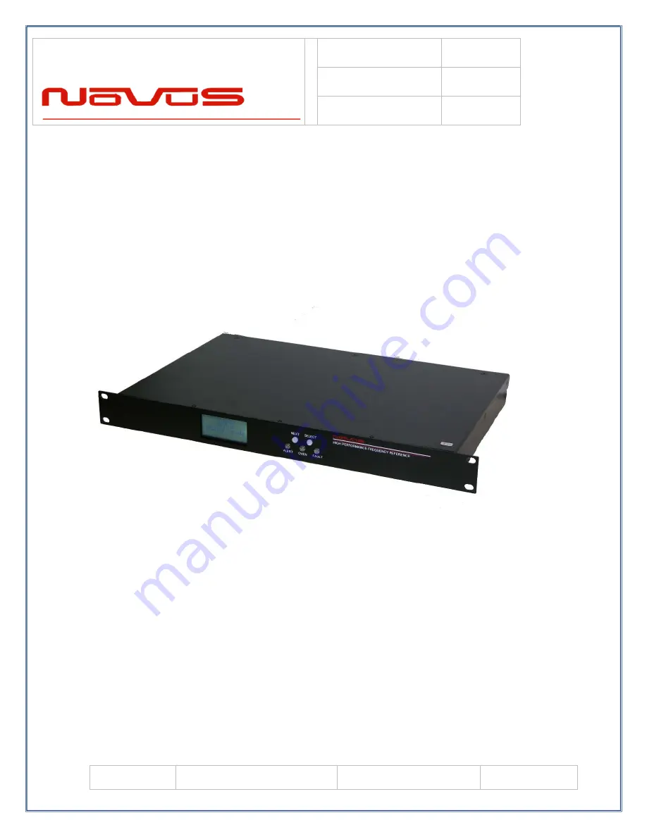
NR2310D-ROG
10 Channel GNSS Locked, Low Noise, Rubidium Frequency
Reference with RS232, Display and optional Ethernet-SNMP
All information provided herein is the proprietary property of Novus Power Products
LLC. The information included may be reproduced without the permission or prior
approval of Novus Power Products LLC for the purpose of operating the equipment.


