background image

Loading a Show

Insert a floppy disk containing a show
file into the floppy disk drive

Press and hold down the + and - keys
on the front panel together, and then
press the GO/ENTER key. The LCD
shows the Super User screen:

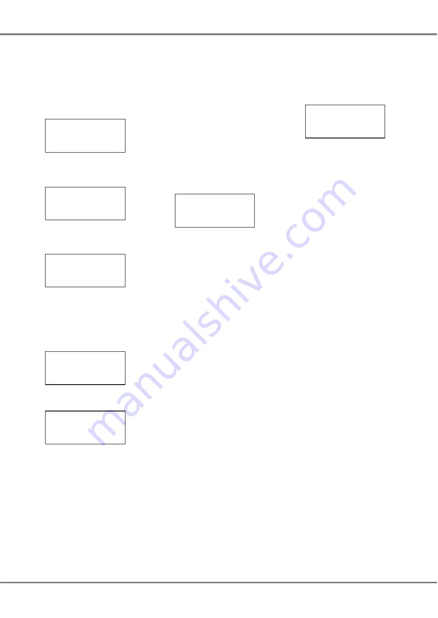
**** SUPER USER ****

{Desk Setup}

{Floppy Disk}
{Clear/Reset}      v

Select the 

Floppy Disk

 option and

press the GO/ENTER key. The Floppy
Disk screen is shown on the LCD:

**** FLOPPY DISK ***

{Load Show}


{Save Show}  
{Format Disk}v

Select the 

Load Show 

option and press 

the GO/ENTER key. The unit reads the 
floppy disk. The LCD shows:

***** LOAD SHOW ****

<    Show01.isf    >
<  10KB 5/2/2001   >

  [Load[   {Cancel} 

If the floppy disk contains several show 
files, use the + and - keys to select the
required show.

Press the GO/ENTER key to load the
selected show onto the unit. While the
show is loading, the LCD shows:

  Loading Show01    
   Please Wait …
     xx% Done.
      [Cancel]

When the show is loaded successfully,
the LCD shows:

                    
   show01 Loaded    


[OK]

Press the GO/ENTER key to return to
the Floppy Disk screen.

Select the 

Exit

 option from the Floppy

Disk screen.  Press the GO/ENTER
key. The LCD returns to the Super
User screen.

Select the 

Exit Super User

 option from

the Super User screen. Press the
GO/ENTER key. The LCD returns to
the Memories screen.

Editing the Show

Any of the editable parameters on the
Memories screen (eg. Fade Up time)
may be adjusted, if required.

Editing a Memory

Use the up and down arrow keys to
select the 

Next

 memory field 

(if not already selected).

Use the + and - keys to select the
required memory to edit.

Use the up or down arrow keys to
select the 

Fade Up

 or 

Fade Down

 time

on the Memories screen.

Current:   1   s    
Next:   <  2   s>
Fade Up:  

<00

:03.0

>

Fade Down:<00:03.0>v

Use the + and - keys to adjust the fade 
time, as required.

Use the up and down arrow keys to
select the 

LTP Fade

 time. Use the +

and - keys to adjust the time.

Use the up and down arrow keys to
select one of the LTP actions 

(

Colour

,

Beamshape

 or 

Position

). Use the +

and - keys to adjust the value.

Use the up and down arrow keys to
select the 

Dwell

 time field. Use the +

and - keys to adjust the time.

Use the up and down arrow keys to
select the 

Trigger

 field. Use the + and - 

keys to adjust the value as required.

If the memory 

Trigger

 is set to Real

Time or Timecode, use the up and
down keys to select the 

Time

 field. 

Use the + and - keys to adjust the time
or timecode as required.

Programming Jumps

To program, edit or delete jumps in the 
memory stack - refer to chapter 3.

Playing Back the Show

The programmed memories in the
show are played back in numerical
order using the GO/ENTER button on
the front panel. The Memories screen
is displayed on the LCD.

Current:   1 s      
Next:     

<2 >

Fade Up:  <00:03.0> 
Fade Down:<00:03.0>v 

Select memory number 1 or the first
programmed memory using the + and -  
keys on the front panel. 

Press the GO/ENTER button. The
outputs will fade from their current
levels to those programmed into the
selected memory, using the transition
times for that memory. 

The 

Current

 and 

Next

 memories are

incremented automatically.

To output the next programmed
memory, press the GO/ENTER button.

Repeat until the end of the memory
stack is reached. Pressing the
GO/ENTER button will then return to
the first programmed memory.

Remote Switches

To play back the show using remote
switches refer to chapter 3. To enable
and configure the remote switches
refer to chapter 4.

Frog Screen Control Panel

To play back the show using a Frog
Screen refer to chapter 3. To enable
and configure the Frog Screen refer to
chapter 4.

SMPTE & MIDI Timecode

To play back the show using SMPTE
or MIDI timecode refer to chapter 3. To 
setup the Frog Box to process SMPTE
or MIDI timecode refer to chapter 4.

Chillinet & iCANnet 

To play back the show using network
messages via Chillinet or iCANnet
refer to chapter 3. To setup the Frog
Box to process network messages
refer to chapter 4.

2 - 2 

Frog Box 73-749-00 Issue 4

Quickstart Tutorial 

Summary of Contents for Frog

Page 1: ...FROG BOX OPERATING MANUAL...

Page 2: ......

Page 3: ...th the limits for a Class A digital device pursuant to part 15 of the FCC rules These limits are designed to provide reasonable protection against harmful interference when the equipment is operated i...

Page 4: ...of Memories 3 4 Playback Front Panel 3 4 Playback Remote Switches 3 4 Playback Frog Screen 3 4 Playback SMPTE MIDI 3 4 Playback Chillinet 3 4 Playback iCANnet 3 4 4 Super User Introduction 4 1 Enterin...

Page 5: ...s in the manual The manual concludes with chapters on the Super User functions other features eg locking the unit monitor screens and technical specification Conventions Throughout this manual the fo...

Page 6: ...or intervention Jumps may be programmed into the memory stack allowing sections of the stack to be repeated or skipped over as required Playback The loaded show may be played back manually using the f...

Page 7: ...d brackets The value of a field can only be edited using the and keys when it is highlighted ie the angled brackets are displayed as flashing In this manual the highlighted field on the LCD is shown i...

Page 8: ...haracters are displayed on the right hand side of the LCD screen to show there are further options available The up and down arrow characters are shown as and v respectively in this manual When the up...

Page 9: ...also assumes that a lighting rig has been set up with dimmers luminaires and moving light fixtures if applicable which are controlled by a standard DMX signal Turning on the Frog Box Connect the DMX...

Page 10: ...one of the LTP actions Colour Beamshape or Position Use the and keys to adjust the value Use the up and down arrow keys to select the Dwell time field Use the and keys to adjust the time Use the up an...

Page 11: ...Memory Numbers Memory numbers can be whole numbers 1 2 3 or numbers with a decimal point eg 1 1 1 2 The possible range of memory numbers in the show is 0 1 to 999 9 Memory Zero Memory Zero is a specia...

Page 12: ...the transition between steps Snap Slow Attack Slow Decay or Crossfade This applies to generic and fixture brightness channels only Colour Action the transition between steps of the colour fixture chan...

Page 13: ...played back via the Go button or automatically the memories are output in numerical order Jumps The Jump function provides the facility to jump to a specific memory on completion of the current memory...

Page 14: ...tup section of Super User see chapter 4 for details Memories with Timecode triggers will then be triggered when the incoming SMPTE or MIDI timecode signal passes the specified start time Memories with...

Page 15: ...ER USER Desk Setup Floppy Disk Clear Reset v The Super User screen contains the following options Desk Setup Floppy Disk Clear Reset Illumination Set Date Time Desk Information Reset DMX Outputs Set C...

Page 16: ...rn to the Desk Setup screen Frog Screen Buttons This function allows the user to configure each of the 130 soft buttons on the Frog Screen control panel Each soft button may be configured to be a Go b...

Page 17: ...w No 1 SAVE Cancel An asterisk is displayed next to the show number if the file does not exist on the floppy disk The Show No defaults to the first available show on the disk 3 Use the and keys to sel...

Page 18: ...on the LCD The LCD returns to the Super User screen Desk Information This Super User function provides the following information on the LCD Serial Number The full serial number of the Frog Box unit S...

Page 19: ...tion via an external monitor The monitor display is text only and has a resolution of 80 characters wide by 50 lines high The monitor is for the display of information only the operational software is...

Page 20: ...on within Super User the monitor screen displays the same data as the LCD on the front panel Remote Switches Screen This screen is displayed on the monitor when in the Remote Switches section of Desk...

Page 21: ...imes are divided into three separate sections hours minutes seconds If the cursor is on any of the three sections a time can be entered from the external keyboard Real times use the 24 hour clock and...

Page 22: ...5 4 Frog Box 73 749 00 Issue 4 Other Features...

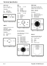
Page 23: ...nal power supply unit is used to power the unit Mains Voltage 230V 10 17 190V 253V 120V 10 17 100V 132V Supply 5V 5A and 12V 1A Parallel Port A 25 pin D type female connector Video Output 15 pin D typ...

Page 24: ...tch 6 Pin 2 Remote Switch 1 Pin 3 Remote Switch 2 Pin 4 Remote Switch 3 Pin 5 Remote Switch 4 Pin 6 Remote Switch 5 Pin 7 Undefined do notconnect Pin 8 0V Common Ground DMX Output Double 5 pin XLR iso...

Page 25: ......
Page 26: ...Tel 44 0 1633 838088 Fax 44 0 1633 867880 e mail sales zero88 com Web www vari lite com 24 hour answerphone...

Reviews: