BNP
®
6012 and 7212 SUCTION BLAST CABINETS
Page 6
© 2019 CLEMCO INDUSTRIES CORP.
www.clemcoindustries.com
Manual No. 27723, Rev. B 04/19
1.9.7 Plastic media:
Plastic and similar lightweight
and/or nonaggressive media are generally not
recommended for suction-style cabinets because the
lower blast velocity of suction blasting combined with the
softer and lighter weight media do not provide the media
impact for productive blasting. Best performance from
plastic media is achieved with pressure blasting,
requiring a pressure vessel with a 60-degree conical
bottom. Refer to Clemco’s Aerolyte
®
cabinet line.
1.9.8
Bicarbonate of soda: Bicarbonate of soda is not
recommended for use in standard cabinets. Bicarb is a one-
use media, which will quickly saturate the filter cartridge(s).
Best performance from bicarb media is achieved with
pressure blasting, requiring a pressure vessel. Refer to
Clemco’s Aerolyte cabinet line for cabinets that are
specifically designed for use with bicarbonate of soda.
1.10
Compressed-Air Requirements
1.10.1
The size of the compressor required to operate
the cabinet depends on the size of the air jet and
blasting pressure. Unless otherwise specified, cabinets
are supplied with a No. 5 (5/32" orifice) jet. Refer to the
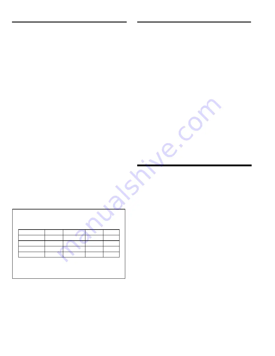
table in Figure 4 to determine air consumption. Consult
with a compressor supplier for suggested compressor
size based on the air consumption.
NOTE:
A separate
air line is required for the reverse-pulse dust collector.
If preferred, remove the plug from the auxiliary air port
(shown in Figure 6) and connect a 1/4″ ID or larger
air
line
to
the
dust
collector
pulse
reservoir/manifold.
Compressed-Air Consumption in CFM
BNP Gun
Jet
Orifice
Nozzle
Orifice
CFM
PSI
No. 4
1/8"
5/16"
21
80
No. 5
5/32"
5/16"
32
80
No. 6
3/16"
3/8"
47
80
*No. 7
7/32"
7/16"
62
80
*No. 8
1/4"
1/2"
86
80
* Using this combination could affect usable media
size; refer to Section 1.9.
Figure 4
1.10.2
The air filter at the air-inlet connection reduces
condensed water from the compressed air. Its use is
especially important in areas of high humidity or when
using fine-mesh media. Moisture causes media to clump
and inhibits free flow through the feed assembly. If the
filter does not remove enough moisture to keep media
dry and flowing, it may be necessary to install an air
dryer or aftercooler in the air-supply line.
1.11
Electrical Requirements
All wiring external of the cabinet is provided by the user
to comply with local electrical codes.
1.11.1
Electrical requirements depend on the size and
phase of the dust-collector exhauster motor. NOTE: Full
load amps (FLA) shown below are for the motor only;
the lights draw less than one amp. Standard cabinets
are supplied as follows:
900 cfm: 2 HP, 208/230/460V, 3-PH, 60 HZ
Supplied with 230-volt control panel unless 460-volt is
specified at the time the order is placed.
FLA 208/5.5, 230/5.6, 460/2.8.
1200 cfm: 5 HP, 208/230/460V, 3-PH, 60 HZ
Supplied with 230-volt control panel unless 460-volt is
specified at the time the order is placed.
FLA 208/12 to 13, 230/12 to 13, 460/6.
1800 cfm: 7.5 HP, 208/230/460V, 3-PH, 60 HZ
Supplied with 230-volt control panel unless 460-volt is
specified at the time the order is placed.
FLA 208/17.8 to 19.6, 230/17.8 to 19.6, 460/8.9.
Refer to Section 2.5 to connect electrical service.
2.0
INSTALLATION
Unless noted otherwise, the sequence of assembly in
Sections 2.2 through 2.8 may be done in any order that
is convenient for the installer.
2.1
General Installation Notes
2.1.1
Refer to Figures 1 (and Figure 2 for optional
RPC-2 Dust Collector) for the general arrangement.
Place all components in a convenient location where
compressed air and electrical service are available. The
cabinet location must comply with OSHA and local safety
codes. Allow for full access to all doors and service
areas, and for efficient handling of large parts. Provide
enough clearance at the dust collector for maintenance
and to remove the dust container. Place freestanding
reclaimers directly behind the cabinet with flex hose
connections and metering valve facing toward the
cabinet to allow for as few bends as possible to prevent
wear. Determine the best location for all components and
position them before making compressed-air connections,
electrical connections, and attaching flex hose.
2.1.2
The cabinet must be placed on a flat level
surface. If the surface is not flat, the cabinet could flex,
causing the door alignment to shift. If the floor is not
level, shim the leg(s) as required to align the door.


