Refrigeration • 23
REFRIgERATION
Electric defrost termination temperature is set at 50°F. At ASHRAE test conditions and 208V defrost heater operation, the observed defrost
durations are typically 30 minutes for frozen food and 40 minutes for ice cream. Electric defrost termination sensors are located in the center of
the evaporator coil.
If it is not possible to terminate the defrost cycle based on a defrost termination thermostat or probe sensing the temperature at the coil, and the
only available temperature probe is sensing the discharge air temperature, then the termination temperature should be set to 65°F, with
0 minutes drip time. Duration will vary depending on how much frost accumulates on the coil.
Freezers with electric defrost are equipped with a safety cutout thermostat (high-limit, snap-disc type) that de-energizes the defrost heater if the
coil temperature exceeds 85°F to provide a secondary safety termination. This thermostat is installed at the right end of the evaporator coil.
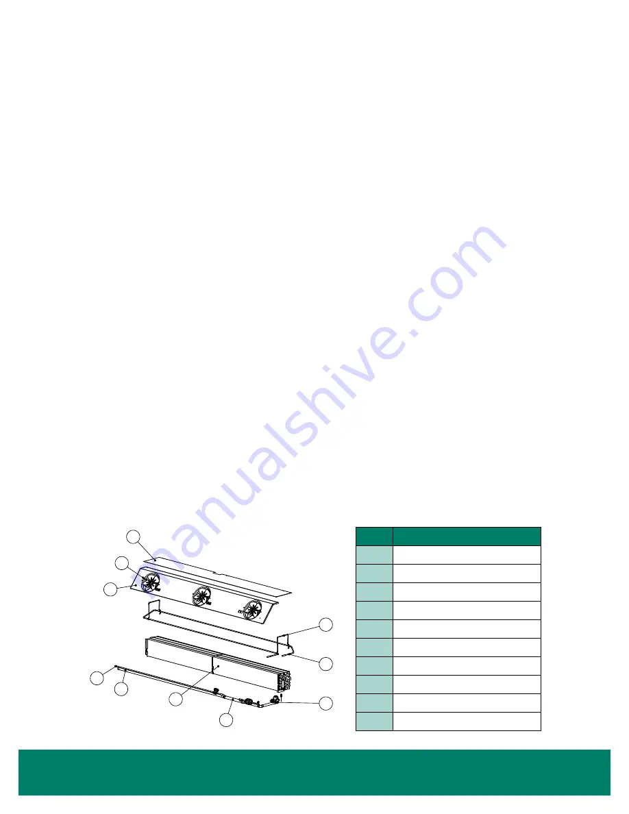
ELECTRIC DEFROST - COMPONENTS
for defrost components.
Half of the u-shaped defrost heater element is located on the front of the coil and the other half is located on the rear of the coil. The front
heater is located approximately 1" off the floor and the rear heater is approximately 2" off the floor. The heater is secured to the coil by stainless
steel heater retaining clips. The heater is fastened to the floor on the right-hand side of the coil. The electric wire leads are connected in a
raceway under the coil cover on the right-hand side of the case.
To replace the heater element, remove the fasteners that hold it to the case floor. First, pull the front leg of the retaining clip away from the coil
and slide the heater out from under the clip. Then the rear leg of the heater can then be removed by raising the retaining clips 2" at a time,
working from right to left on the coil. Repeat this process until the retaining clips are free of the coil. The heater will slide up with the retaining
clip. Install the replacement heater in reverse order of how it was removed.
Cases set up for 3-phase defrost use 2 additional heater elements (
). These heater elements can be replaced by
following the same process as for single-phase defrost cases.
Each freezer has factory-set limit thermostats attached to the right end of the evaporator coil to regulate the operation of the evaporator fans
and defrost heater. A second limit thermostat may be included to control the lights.
!
CAUTION!
OPERATInG THE LIMIT THERMOSTATS CAuSES THE EVAPORATOR FAnS TO REMAIn OFF unTIL THE
COMPRESSOR IS OPERATInG AnD THE COIL TEMPERATuRE IS BROuGHT BELOW THE THERMOSTAT CuT-In
SETTInG. SuPERHEAT MuST BE SET CORRECTLY FOR PROPER THERMOSTAT OPERATIOn.
ITEM
PART
1
Coil Cover
2
Fan
3
Liquid Line
4
Suction Line
5
Fan Housing
6
Heat Exchanger
7
TXV
8
Heater Element
9
Heater Clip
10
Defrost Termination Probe
FIGURE 38: Electric Defrost Components


