ZT MK2
34
Connection of controller and warning lights
www.zepro.com
6
Connection of controller and warning lights
6.1
Cable grommet
6.1.1
Before installing cabling
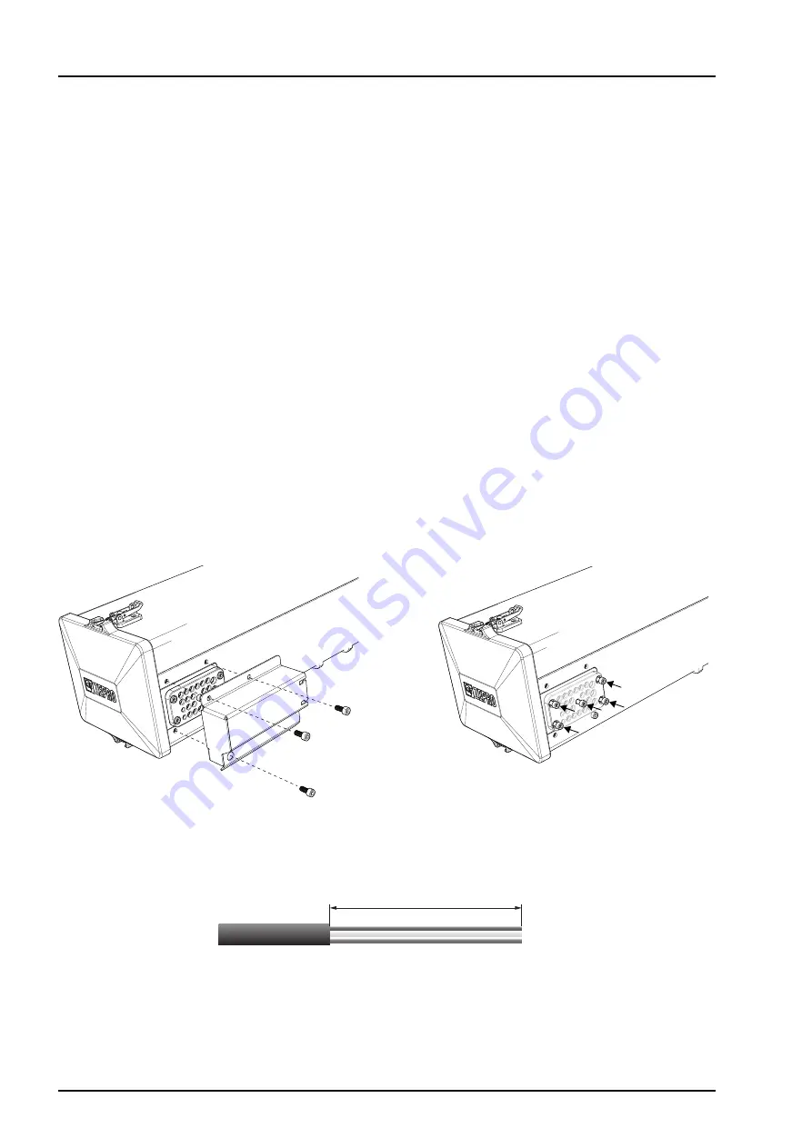
To be able to install cables in the cable grommet, its protective cover must be removed and the five screws
loosened.
1. Disconnect the cable grommet’s protective cover, which is secured with three screws, see Picture 46.
2.
Loosen the five screws on the cable grommet, see
Picture 48. Cables can now be installed/removed/ad-
justed in the grommet. When installing the cable, it should be done together with existing cabling using
cable ties. Ensure the length of the cable is sufficient for moving the control card. The outer sheathing on
cables that connect to the control card must be stripped 350 mm, see Picture 47.
6.1.2
After installing cabling
1.
When all cables are suitably located in the cable grommet, tighten the five screws, see
Picture 48.
Tightening torque: 5 Nm.
2. Install the cable grommet’s protective cover with the three supplied bolts, see Picture 46.
Tightening torque: 8 Nm.
Picture 46. Fasten the cable grommet’s
protective cover with three screws
350 mm.
Picture 47. The outer sheathing on cables that connect to the control card have to be stripped 350 mm.
Picture 48.
Cable grommet's five screws


