background image

P A G E   4

3-WireRev6/00

IMPORTANT SAFETY INSTRUCTIONS

(Continued from previous page)

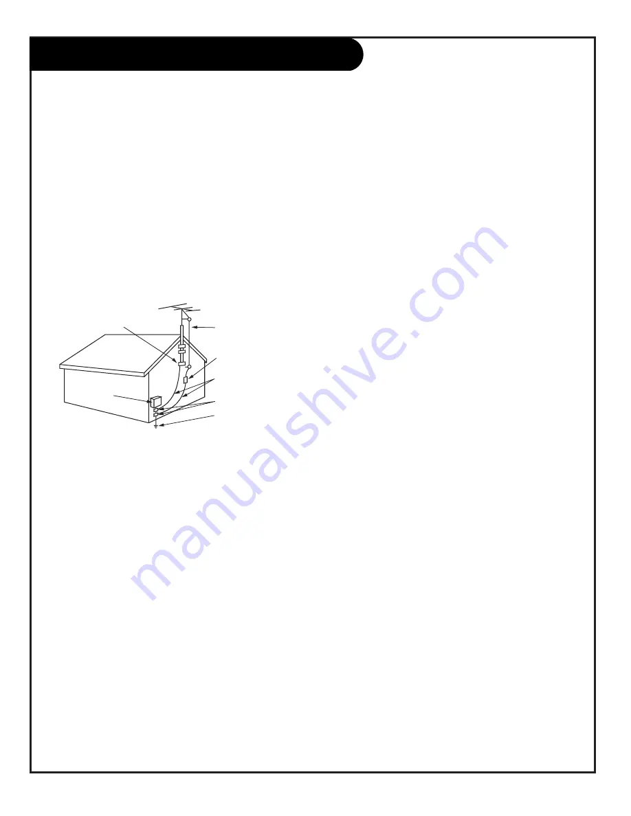
14. Outdoor Antenna Grounding

If an outside antenna or cable system is connected to the
product, be sure the antenna or cable system is grounded so
as to provide some protection against voltage surges and
built-up static charges. Article 810 of the National Electrical
Code (U.S.A.), ANSI/ NFPA 70 provides information with
regard to proper grounding of the mast and supporting
structure, grounding of the lead-in wire to an antenna dis-
charge unit, size of grounding conductors, location of
antenna-discharge unit, connection to grounding electrodes,
and requirements for the grounding electrode.

15. Lightning

For added protection for this product (receiver) during a
lightning storm, or when it is left unattended and unused
for long periods of time, unplug it from the wall outlet and
disconnect the antenna or cable system. This will prevent
damage to the product due to lightning and power-line
surges.

16. Power Lines

An outside antenna system should not be located in the
vicinity of overhead power lines or other electric light or
power circuits, or where it can fall into such power lines or
circuits. When installing an outside antenna system, extreme
care should be taken to keep from touching such power
lines or circuits as contact with them might be fatal.

17. Overloading

Do not overload wall outlets and extension cords as this can
result in a risk of fire or electric shock.

18. Object and Liquid Entry

Never push objects of any kind into this product through
openings as they may touch dangerous voltage points or 

short-out parts that could result in a fire or electric shock. 
Never spill liquid of any kind on the product.

19. Servicing

Do not attempt to service this product yourself as opening
or removing covers may expose you to dangerous voltage or
other hazards. Refer all servicing to qualified service person-
nel.

20. Damage Requiring Service

Unplug this product from the wall outlet and refer servicing
to qualified service personnel under the following condi-
tions:

a. If the power-supply cord or plug is damaged.

b. If liquid has been spilled, or objects have fallen into the

product.

c. If the product has been exposed to rain or water.

d. If the product does not operate normally by following

the operating instructions. Adjust only those controls that
are covered by the operating instructions as an improper
adjustment of other controls may result in damage and will
often require extensive work by a qualified technician to
restore the product to its normal operation.

e. If the product has been dropped or the cabinet has been

damaged.

f. If the product exhibits a distinct change in performance.

21. Replacement Parts

When replacement parts are required, be sure the service
technician has used replacement parts specified by the man-
ufacturer or have the same characteristics as the original
part. Unauthorized substitutions may result in fire, electric
shock, or other hazards.

22. Safety Check

Upon completion of any service or repairs to this product,
ask the service technician to perform safety checks to deter-
mine that the product is in proper operating condition.

23. Wall or Ceiling Mounting

The product should be mounted to a wall or ceiling only as
recommended by the manufacturer. The product may slide or
fall, causing serious injury to a child or adult, and serious
damage to the product.

24. Heat

The product should be situated away from heat sources such
as radiators, heat registers, stoves, or other products
(including amplifiers) that produce heat.

Antenna Lead in Wire

Antenna Discharge Unit
(NEC Section 810-20)

Grounding Conductor
(NEC Section 810-21)

Ground Clamps

Power Service Grounding
Electrode System (NEC
Art 250, Part H)

Ground Clamp

Electric Service

Equipment

Example of Grounding According to National Electrical
Code Instructions

NEC - National Electrical Code

Summary of Contents for C32V23 - 32" Flat-Screen Integrated HDTV

Page 1: ...Copyright 2002 Zenith Electronics Corporation Operating Guide Warranty Model Numbers C32V23 C36V23 C34W23 Digital TVs...

Page 2: ...installation This equipment generates uses and can radiate radio frequency energy and if not installed and used in accordance with the instruction manual may cause harmful interference to radio commu...

Page 3: ...he product Any mounting of the product should follow the manufacturer s instructions and should use a mounting accessory recommended by the manufacturer 8 Transporting Product A product and cart combi...

Page 4: ...age or other hazards Refer all servicing to qualified service person nel 20 Damage Requiring Service Unplug this product from the wall outlet and refer servicing to qualified service personnel under t...

Page 5: ...30 EZ Picture Custom Normal Digital Preset Night Time Movie Weak Signal Video Game Sports Contrast Brightness Color Tint Sharpness Color Temp Z View Audio Menu 31 Audio Mode Mono Stereo SAP EZ SoundRi...

Page 6: ...page 37 English is selected 8 Use EZ Scan to search for all channels in your area See page 18 9 Turn video source equipment on 10 Select viewing source for TV See pages 21 and 29 11 Fine tune source...

Page 7: ...Audio Video or S Video equipment to these jacks See pages 10 11 12 HD IN 1080i Connect high definition component video equip ment here EDTV Set top Box 1080i HDTV Set top Box 1080i See page 14 ANTENNA...

Page 8: ...have a 75 ohm RF cable then you don t need any adapters A 300 to 75 ohm adapter is not included with the TV 300 TO 75 OHM ADAPTER Typical TV Back Flat Wire 300 ohm Antenna 300 75 ohm Adapter ANTENNA...

Page 9: ...ox In Out RF Coaxial Wire 75ohm 3 4 output switch Typical TV Back ANTENNA CABLE 1 Locate the Antenna Cable jack on the back of the TV Connect the cable service wire that runs from the wall or cable bo...

Page 10: ...VCR Back AV Panel output switch Typical Antennas Flat or Round Wire Flat Wire 300 ohm 300 75 ohm Adapter RF Coaxial Round Wire 75ohm Connect your VCR to the Video 1 or Video 2 set of input jacks Locat...

Page 11: ...3 4 VCR Back VCR Back AV Panel output switch Typical Cable TV Wall Jack Cable Box In Out 3 4 output switch Cable service with or without a cable box Connect your VCR to the Video 1 or Video 2 set of...

Page 12: ...nnected to a Super VHS VCR through the S Video Input located on the front or rear source connection panels on your TV Hook up your S VHS VCR to your Zenith TV according to the diagram shown at the rig...

Page 13: ...lled by a switch Do not attempt to operate it on DC power Press POWER to turn TV on On the remote press SOURCE repeatedly until DVD IN is displayed Or use the Source menu to choose DVD IN Hook Up Comp...

Page 14: ...urce menu to choose HD In Hook Up HD Equipment Connecting high definition equipment 1 2 3 120 V AC 60 Hz 4 TV Back Pr Pb Y R L Pr Pb Y R L R L R L R L RGB VIDEO 2 IN VIDEO 1 IN MONITOR OUTPUT AUDIO AU...

Page 15: ...s on how to turn the TV s internal speakers off and on Select Audio Video Input on the external device to see the image and hear the sound from the TV Audio Video Signal Output Output to Audio Video d...

Page 16: ...al Input Digital Audio Equipment CALIBRATION Connect one end of an optical cable to the TV Digital Audio Optical Output port Connect the other end of the optical cable to the digital audio optical inp...

Page 17: ...Right buttons to adjust the sound level quieter or louder to your preference Temporary Connections Connect your video equipment like a Camcorder to the Front Video input jacks On the remote control us...

Page 18: ...or further band information contact your cable service provider Use EZ Scan to automatically find active channels and store them in the TV s memory EZ Scan finds active channels being received by the...

Page 19: ...lects channels directly and enters numeric values for some options MENU Shows on screen menus for TV mode See page 20 VIDEO Selects different picture settings remote control part number MBR4286 P124 0...

Page 20: ...ectional arrow to highlight an option like the CONTRAST adjustment bar then press the Right arrow You can select other menu options like COLOR TEMP using the UP or DOWN directional arrows Once the opt...

Page 21: ...In on TV front Jackpack S Video Input jack use with front Audio Input jacks DVD IN on TV back Jackpack 480i Set of Component Audio Video Input jacks HD In on TV back Jackpack Set of component Audio Vi...

Page 22: ...ages 18 25 29 Sets the TV up and adjusts the basic features EZ Scan page 18 Automatically finds and stores all available channels in your viewing area tune in those channels using Channel Up Down Ch E...

Page 23: ...appear in English Spanish French EZ Demo page 38 On Off Demonstrates the on screen menus that control the TV s setup and operational features LOCK SYSTEM pages 39 40 41 Allows parents to block progra...

Page 24: ...und Volume Display Press the VOLUME key on the remote control to see the sound level status display Channel Time Display Press ENTER on the remote control to view the Channel Time incoming audio signa...

Page 25: ...atedly to scroll your Surf chan nels Press MENU use the Up Down arrow to select the SETUP menu then press ENTER or the right arrow Use the Up Down arrow to highlight the Ch Edit option then press ENTE...

Page 26: ...f the DTV signal being received DTV Input Signal Menu 1 2 3 EZ Scan Ch Edit DTV Signal Tilt Ch Label Input Source SETUP VIDEO AUDIO LOCK SPECIAL TIME Bad Normal Good EZ Scan Ch Edit DTV Signal Tilt Ch...

Page 27: ...nus and return to TV viewing 1 2 3 4 Menu Prev EZ Scan Ch Edit DTV Signal Tilt Ch Label Input Source SETUP VIDEO AUDIO LOCK SPECIAL TIME EZ Scan Ch Edit DTV Signal Tilt Ch Label Input Source SETUP VID...

Page 28: ...ENTER Tune to the channel you want to label with a logo using the Channel Up Down arrows Use the Up Down Left Right arrows to select a logo for the chan nel then press ENTER The logo appears above th...

Page 29: ...urn to TV viewing Choose the picture and sound you want to see and hear for the main screen Selecting Input Sources A 1 2 3 Analog DTV Video 1 Video 2 Front Video DVD In HD In Menu Prev EZ Scan Ch Edi...

Page 30: ...brighter the picture appears Brightness Increases or decreases amount of white in the TV picture Color Adjusts levels of all colors in the TV picture Tint Adjusts the relative amounts of red and green...

Page 31: ...nce Press QUIT to return to TV viewing or press MENU and repeat from step two to set the other menu options Your options are Audio Mode Choose from Stereo sound Mono sound or 2nd Audio SAP EZ SoundRit...

Page 32: ...IME SETUP Manual Mode User sets the Clock options Year Set the current year Date Set the Month and Date Time Set the Hours Minutes and AM or PM Auto Mode TV sets the clock but the user can enter the m...

Page 33: ...ng the TV Turn On Time With the Time menu selected use the Up Down arrows to choose the On Timer option then press ENTER or the Right arrow button Use the Left Right arrows to move through the menu an...

Page 34: ...60 min 90 min 120 min 180 min 240 min Sleep Timer Use the TIMER button to choose a preset time from 10 minutes to 4 hours for the TV to automatically turn itself off Using the Sleep Timer Menu Selecti...

Page 35: ...ange the pic ture aspect ratio to the for mat required by the selected source Aspect Ratio Analog Caption Language EZ Demo VIDEO AUDIO LOCK SPECIAL TIME Menu Prev Set By Program 16 9 4 3 SETUP EZ Scan...

Page 36: ...Down arrow to choose Analog Caption then press ENTER or the Right arrow button Use the Up Down arrow to select an option from the Analog Caption menu Caption Text Off Caption 1 Caption 2 Caption 3 Ca...

Page 37: ...utton Use the Up Down arrow to select the Menu Language option on your screen then press ENTER or the Right arrow button Use the Up Down arrow to choose any of the following options English Spanish or...

Page 38: ...select the EZ DEMO option When you press ENTER or the Right arrow button EZ Demo will start and continue to run Press QUIT to stop EZ Demo remove menu and return to TV viewing Aspect Ratio Analog Capt...

Page 39: ...individual parameters such as Age Dialog Language Sex Violence or in the TV Rating Children option Fantasy Violence Select a secret password in the Set Password option Use the number keys on the remo...

Page 40: ...try Block Ch Movie Rating TV Rating Children TV Rating General Aux Block VIDEO AUDIO LOCK SPECIAL TIME Menu Prev On Off SETUP EZ Scan Ch Edit DTV Signal Tilt Ch Label Input Source SETUP VIDEO AUDIO LO...

Page 41: ...onsidered suitable for all children under 7 years old TV Y7 Children 7 and over Considered suitable for children over 7 may contain Fantasy Violence Scenes Lock System Menu Structure Lock System menus...

Page 42: ...your Zenith remote control 5 3 Turn on the device you want to program On the chart on page 46 47 find the type of device you re programming and then find the brand name Write down the three number cod...

Page 43: ...Audio Tuner Receiver or Amplifier See Audio Tuners Amp list on page 47 CABLE BOX VOLUME Some cable boxes have volume controls AUX Auxiliary equipment Mode Sound Switch Setup 1 2 3 4 5 If you can t fin...

Page 44: ...e to work up to 4 different devices if all modes are programmed Not all devices will work with your Zenith remote control 1 With a small blunt object press and hold PRG for about three seconds When th...

Page 45: ...8 9 MENU REWIND F FWD RECORD ENTER SIGNAL AUDIO CC QUIT SOURCE PAUSE TIMER PLAY STOP RATIO VIDEO Turn on the device you want to program the remote to operate With a small blunt object press and hold...

Page 46: ...WOOD 004 TEKNIKA 002 003 004 006 024 028 031 043 072 077 101 103 143 TELEFUNKEN 037 046 086 087 TELERENT 072 TERA 172 TMK 004 116 TOSHIBA 007 015 030 040 051 062 101 138 TOTEVISION 143 UNIVERSAL 008 0...

Page 47: ...EUROPLUS 224 FUJITSU 127 131 132 137 243 244 GENERAL INSTRUMENT 113 114 126 139 141 169 211 HITACHI 144 177 HOUSTON TRACKER 143 147 149 161 167 214 HUGHES 178 HYTEK 163 JANIEL 170 241 JERROLD 171 KATH...

Page 48: ...t 6 VCR Digit 6 Cable Digit 6 AUX Digit 6 7 TV Digit 7 VCR Digit 7 Cable Digit 7 AUX Digit 7 8 TV Digit 8 VCR Digit 8 Cable Digit 8 AUX Digit 8 9 TV Digit 9 VCR Digit 9 Cable Digit 9 AUX Digit 9 0 TV...

Page 49: ...et the cabinet air dry before turning the TV on Use a quality wood cleaner and polish This will protect the TV from dirt and dust as well as keep the cabinet looking new If you leave your TV dormant O...

Page 50: ...ence Try different channel Turn off interfering appliance 17 19 Scrambled CATV channel Tune to unscrambled channel 17 19 No CATV reception Wrong cable band Try Std HRC IRC or contact cable company for...

Page 51: ...ed in your area set to Off 32 Time does not set automatically Set clock manually or try tuning to PBS station 32 Auto Mode doesn t work Set PBS station on Clock menu 32 Auto Clock doesn t work Turn Au...

Page 52: ...t Ratio Use correct aspect ratio for source s image 35 No picture or sound Wrong source selected on TV Select correct source equipment 19 Source equipment turned off Turn source equipment on Tape or D...

Page 53: ...as UHF and VHF ANTENNA The physical receiver of television signals sent over the air A large metal piece of equipment does not always have to be visible for your home to be using an antenna DELETED L...

Page 54: ...P A G E 5 4 206 3767 Notes...

Page 55: ...P A G E 5 5 206 3767 Notes...

Page 56: ...ou may also have other rights that vary from state to state THIS LIMITED WARRANTY DOES NOT APPLY To damages or operating problems that result from shipping installation adjustment of user controls cal...

Reviews: