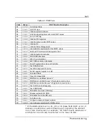

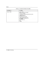

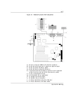

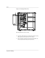
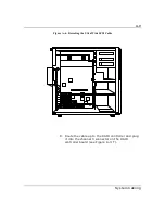


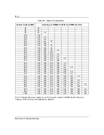


A-3
System Cabling
Figure A-1. Standard System Cable Configuration
A— Device internal SCSI termination resistors
B— Narrow SCSI devices in upper peripheral bays
C— Narrow SCSI interface cable
D— Narrow SCSI connector (50 pin)
E— Internal SCSI termination resistors (not installed
when internal narrow SCSI devices are used)
F— 3 1/2-inch diskette drive
G— 2nd diskette drive (optional)
H— Diskette interface cable
I— Diskette drive connector
J— Ultra wide SCSI connector (68 pin)
K— Ultra wide SCSI interface cable
Summary of Contents for MT2000
Page 1: ...Server MT2000 U s e r s G u i d e...
Page 6: ...raham...
Page 8: ...Bill Graham...
Page 9: ...Chapter 1 Introduction Contents Organization 1 Notational Conventions 3...
Page 10: ...Bill Graham...
Page 53: ...1231231 Billy Graham...
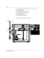
Page 81: ...4 28 Configuring Your System Figure 4 2 System Board Jumpers...
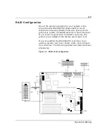
Page 141: ...5 53 Upgrades and Options Figure 5 25 Removing the Rear Fan modules...
Page 143: ...dfgdfg...
Page 171: ...Bill GrahamBill Graham...
Page 182: ...Appendix B Memory Configurations Contents Memory DIMM Configurations 1...
Page 183: ...Bill Grahamaerrterterter...
Page 186: ...Appendix C Option Boards Contents Introduction C 1...
Page 188: ...Appendix D Devices Contents Introduction 1...
Page 190: ...Appendix E Network Operating Systems Contents Introduction 1...
Page 193: ...rtyrtyrtyrtyry...
Page 203: ...8 Glossary...
Page 204: ......
Page 205: ...101843 1...


