


25
11. Shutting down the system
11.1.
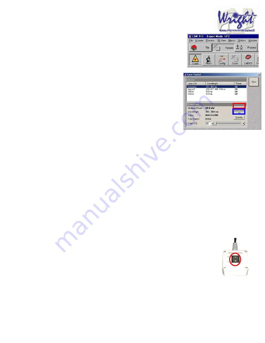
Turn off lasers
Click the
Acquire
toolbar button, the
Laser
button in the sub-
toolbar.
In the
Laser control
window turn each laser
Off
or to
Standby
if somebody is using the system within the next hour.
If you have used the UV laser, switch off the black switch in the
white frame located on the front of the UV laser power supply.
Do not touch any of the cooling unit settings.
11.2.
Remove Specimen and clean
microscope
Wipe off water from objective and specimen.
Move to a low power objective (5× or 10×) objective. Raise the
stage using the buttons on the left had side of the microscope base.
If you switch off the system while the stage is lowered the ‘top’ of the focus range will be
reset to that position when the microscope is next turned on. This will mean the ‘top’ will
need resetting and could result in damage to the $12,000 63× objective.
Turn off the epifluorescence lamp.
Cover the microscope avoiding the hot lamp housing.
11.3.
Exit the software
Exit the Zeiss LSM .
A message will come up reminding you not to power down the system until the laser is
cool. Click
OK
.
If you have left the lasers on for the next user, you will also be asked whether you want
the lasers switched off. Click
No
.
Read then close the WCIF Exit screen.
Burn your data to CD or copy across network (once installed).
Once you have finished with the computer, LOGOUT. If you do not logout, the system
will continue to charge time to your account.
11.4.
Power down the system
If nobody has booked for the next hour, please shutdown the system If the next
person is the last booking of the day, please call them and confirm that they will
be using it. This requires that the
remote control
be switched off and the
compressed air shut down.


