


07/05
11
Scanning an image
•
Click on the
Scan
button in the
Acquire
subordinate toolbar to open the
Scan
Control
window.
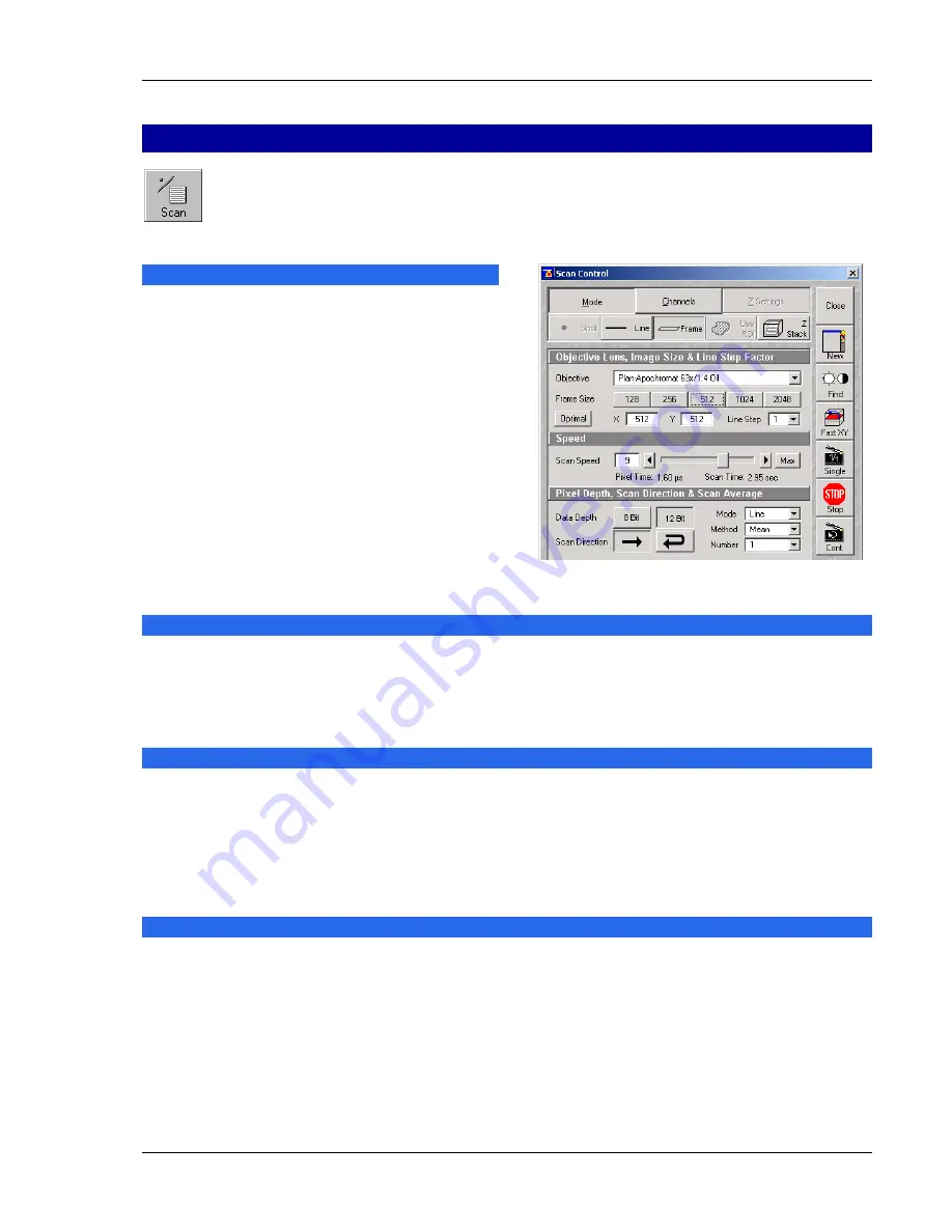
The
Scan Control
window appears (Fig. 16).
Setting the parameters for scanning
•
Select
Mode
in the
Scan Control
window.
•
Select the
Frame Size
as predefined number of
pixels or enter your own values (e.g. 300 x 600)
in the
Objective Lens, Image Size & Line
Step Factor
panel. Click on the
Optimal
button for calculation of appropriate number of
pixels depending on N.A. and
λ
.
The number of pixels influences the image
resolution!
Note:
When using an Axioskop 2 FS
MOT
, indicate
the objective that is in use in the
Scan Control
window. This ensures correct calculation of
pinhole, Z stack optimization etc.
Adjusting the scan speed
•
Use the slider in the
Speed
panel (Fig. 16) to adjust the scan speed.
A higher speed with averaging results in the best signal to noise ratio. Scan speed 8 usually produces
good results. Us speed 6 or 7 for superior images.
Choosing the dynamic range
•
Select the dynamic range 8 or 12 Bit (per pixel) in the
Pixel Depth, Scan Direction & Scan Average
panel (Fig. 16).
8 Bit will give 256 gray levels, 12 Bit will give 4096 levels. Publication quality images should be acquired
using 12 Bit data depth. 12 Bit is also recommended when doing quantitative measurements or when
imaging low fluorescence intensities.
Setting the scan averaging
Averaging improves the image by increasing the signal : noise ratio. It can be achieved line by line or
frame by frame. Frame averaging helps reduce photobleaching, but does not give quite such a smooth
image.
•
Select the
Line
or
Frame
mode for averaging.
•
Select the desired scan average method
Mean
or
Sum
in the
Method
selection box.
If you are using the
Mean
method, the image information is generated by adding up all scans pixel by
pixel and then calculating the mean value.
Fig. 16
Scan Control window, Mode settings
Summary of Contents for LSM 510 Inverted
Page 16: ......