background image

DuraMax Installation site requirements

20

Limit curves of permissible floor vibrations at the installation site

Explanation for the diagrams

The following diagrams shown the frequency-dependent limit values for the coordinate measuring machine. However,
these are non-binding and apply only to the specified combination of size and probe. Furthermore, the following re-
quirements must be met (otherwise minor deviations must be expected and a certain distance to the limit values
should be maintained):

No loading workpieces >10% of CMM weight

Stylus tip distance <100 mm relative to the stylus mount on contact probes

If there are any harmonic floor vibrations (sinusoidal oscillations, e.g. caused by nearby, rotating machine tools), the
limit values must be compared with the square mean (RMS value) of the measured floor vibrations. If there are any
pulse-shaped floor vibrations (e.g. caused by a nearby press), the limit values must be compared with the maximum
value (peak hold) of the measured floor vibrations. If there are two peaks near each other in the frequency spectrum
(regardless of the excitation direction), the amplitudes of these peaks must be added and compared with the limit
curves.

If none of the given diagrams applies to your configuration, the diagrams for other sizes can be used for orientation.
Please contact your ZEISS representative if you require more information about this.

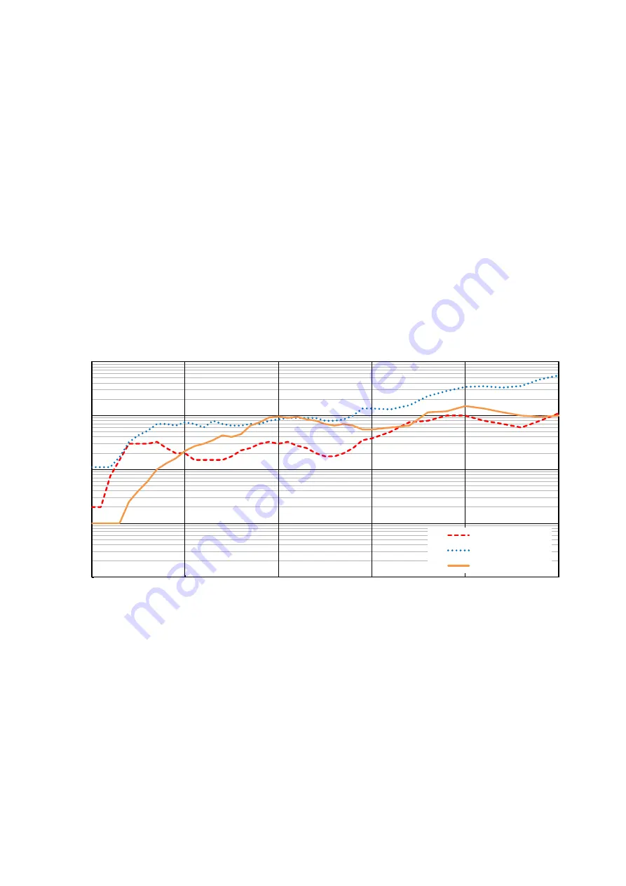
Permissible foundation acceleration for DuraMax

Note:

 Acceleration values above the corresponding curve require additional damping.

0,1

1

10

100

1000

0

10

20

30

40

50

Vibration acceleration  [mm/ s ²]

Frequency [Hz]

X axis horizontal

Y axis horizontal

Z axis vertical

Summary of Contents for DuraMax

Page 1: ...DuraMax Installation site requirements Coordinate measuring machine CMM...

Page 2: ...DuraMax Installation site requirements 2020 12 01 61221 3011202...

Page 3: ...n 9 General protection measures 9 Doorway dimensions in the measuring lab 9 Room height of the measuring lab 9 Floor 9 Floor plan 9 Floor load 9 Vibrations at the installation site 9 Environmental con...

Page 4: ...standard base 16 DuraMax with ShopFloor base 17 Securing the shopfloor base 18 DuraMax measuring table with threaded holes 19 Limit curves of permissible floor vibrations at the installation site 20...

Page 5: ...s comprised of the following components Coordinate measuring machine CMM Controller integrated Control console Base optional Data system and peripheral devices optional Note on data systems NOTE Data...

Page 6: ...lifted below the center of gravity label the cargo may tip over and be ir reparably damaged The center of gravity of the packaged CMM is located outside of the center of the shipping pallet and is lab...

Page 7: ...ctive cover at its final installation site for at least 24 hours before the cover is opened or removed This is the only way to prevent rust damage due to condensation Only a ZEISS service technician o...

Page 8: ...located when properly secured with transport braces and under the supervision of our system specialists Preparatory measures The measuring table must be clear Remove probe The control console and the...

Page 9: ...pFloor base for the dimensions and information Floor plan If you create a floor plan on a CAD system you can produce a DXF and or a DWG file containing the dimensions If you require further assistance...

Page 10: ...d in VDI VDE 2627 Environmental conditions for operational readiness The following conditions must be met to properly operate the coordinate measuring machine Permissible humidity without condensation...

Page 11: ...EMC The CMM is a class A device and may cause radio interference in living areas In such cases opera tors may be required to take adequate measures at their own expense For peripheral devices e g comp...

Page 12: ...recommend installing the connection in accordance with the following diagram Note Comply with applicable national regulations L N PE C16A Customer installation of local voltage suggested Circuit brea...

Page 13: ...equires an Internet connection An Internet connection is not required for the installation of the CMM Network topology System components are networked during start up by a ZEISS service engineer or a...

Page 14: ...e g distance to the wall and required connections can be seen in the drawing on the next page Weight Value CMM kg 350 Workpiece max kg 100 Floor load Mean pressure on the support surfaces Please chec...

Page 15: ...power supply for data system e g computer printer monitor 7 Controller 8 Additional housing on base only with rotary table option 9 Control console tray removable 10 Table optional for data system Mi...

Page 16: ...plug screws are included with delivery to anchor the standard base to the floor foundation The plug screws must be anchored into the foundation There is a risk of tipping if not properly anchored If...

Page 17: ...or monitor keyboard and mouse 6 Control console tray removable 7 Controller 8 Additional housing on base only with rotary table option Minimum distance for personal safety and service 600 mm for perma...

Page 18: ...965 Position of the boreholes for the shopfloor base top view M 1 10 dimensions in millimeters Three fastening brackets 1 and three plug screws are included with delivery for fastening the shopfloor...

Page 19: ...allation site requirements 19 DuraMax measuring table with threaded holes 494 x 494 0 100 0 1 100 0 1 100 0 1 100 0 1 200 0 1 200 0 1 200 0 1 200 0 1 0 M10 25x Measuring table M 1 4 all dimensions in...

Page 20: ...s the limit values must be compared with the square mean RMS value of the measured floor vibrations If there are any pulse shaped floor vibrations e g caused by a nearby press the limit values must be...

Page 21: ...DuraMax Installation site requirements 21...

Page 22: ...DuraMax Installation site requirements 2020 12 01 61221 3011202...

Reviews: