background image

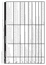
TYPE 

LED FAILURE

A1

DR

Y RUNNING


Failure verification

 Final f

ailure

A2

OVER

-INTENSIT

Y


Failure verification

 Final f

ailure

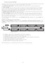
ALARMS 

FOR 

SINGLE 

ASSEMBLY:

In 

case 

of 

simultaneous 

alarms, 

quit 

the 

automatic 

mode 

and 

go 

to 

manual 

mode, 

pressing 

 the 

pushbut

ton 

AUTOMATIC ON/OFF

 (led 

light 

PUMP 

will 

turn 

off

). 

Using 

key


p

q

will 

be 

display

ed 

the 

succesiv

alarms. 

Once 

visualized, 

for 

leaving 

the 

menu,  

press 

ENTER

 returning 

to 

MANUAL

 mode. 

A6

EXCES

SIVE TEMP

.

 Final f

ailure

A7

SHOR

TCIRCUIT

 Final f

ailure

A8

OVERVOL

TAGE


Failure verification

A9

UNDERVOL

TAGE


Failure verification

BL

ANK

SCREEN

A5

TRANSDUCER

 Final f

ailure

A3

DISCONNECTED P

.

 Final f

ailure

SOLUCIÓN

DESCRIPTION

If the system detects dry running  during more than 10 seconds, it will  stop the pump and the AR

(Automatic R

esetT

est) will be 

activ

ated. 

The 

system 

pumps 

are 

protected 

against 

ov

er 

currents 

by 

mean 

of 

the 

intensit

values 

established 

in 

the 

installation 

menu. 

These 

ov

er 

currents 

are 

produced 

gener

ally 

by 

dysf

unctions 

in 

the 

pump 

or 

in 

the 

electric 

supply.

The 

ZP 

Speedcontrol 

Comfort


has 

an 

electronic 

system 

for 

protection 

against 

short 

circuits 

as 

well 

as 

fuse 

of 

20 

A.

The 

ZP 

Speedcontrol 

Comfort


has 

an 

electronic 

safety 

system 

against 

short circuits as well 

as 

20 

fuse.

The 

transducer 

damages 

are 

showed in 

the  

ZP 

Speedcontrol 

Comfort

´s 

LCD 

screen. 


The 

system 

has 

cooling 

device 

to 

keep 

the 

INVER

TER 


in 

optimum 

working 

conditions.  

The 

ZP 

Speedcontrol 

Comfort

 has 

an 

electronic safety 

system 

against 

overvoltages.

The 

ZP 

Speedcontrol 

Comfort


has 

an 

electronic 

safety 

system 

against 

too 

low 

supply voltages.

Blank screen. 

After 5 minutes AR

T system will start again the  pump 

during 30 seconds, trying to restore the system. In  case of persistent lack of w

ater

, it will try it again 

ev

ery 30 minutes f

or 24 hours. If after all these cy

cles 

, the system still detects lack of w

ater

, pumps will 

remain permanently out of order until the damage will  be repaired.

When 

detecting 

the 

thermal 

failure, 

the 

pump 

will 

be 

automatically 

stopped. 

The 

 system 

will 

try 

again 

to 

restart 

the 

 pump 

when 

the 

demand 

of 

consumption 

require 

it. 

The 

control 

system 

will 

carry 

out 

at

tempts 

in 

this 

circumstances. 

If 

the 

system 

remain 

lock

ed 

after 

the 

4th 

at

tempt, 

the 

 pump 

will 

remain 

definitiv

ely 

out 

of 

order

.

SYSTEM REACTION

The 

device 

is 

disconnected.

The 

device 

oper

ation 

is 

interrupted.

If 

an 

ex

cessiv

temper

ature 

is 

reached 

the 

own 

system 

leav

es 

the 

in

verter 

out 

of 

service 

and 

as 

consequence 

the 

pump 

too

.

The pump remains stopped f

or 10". Then it starts 

again - 4 at

tempts. If the problem is not solv

ed, the  

pump will remain definitiv

ely out of order


IIn 

case 

of 

ov

erv

oltage 

the 

system 

remains 

stopped 

until 

an 

adequate 

value 

of 

voltage 

is 

reached. 

In 

this 

case,  

the 

system 

is 

automatically 

restored.


In 

case 

of 

underv

oltage 

the 

system 

remains 

stopped 

until 

an 

adequate 

value 

of 

voltage 

is 

reached. 

In 

this 

case,  

the 

system 

is 

automatically 

restored.

Dry 

running, 

 it 

has 

been 

activ

ated 

the 

saf

et

system: 

you 

should 

verif

the 

feeding 

of 

the 

hydr

aulic 

network. 

The 

pumps 

can 

be 

primed 

using 

the 

push-but

ton 

ST

AR

T/ST

OP 

( the 

led 

light 

AUT

OMA

TIC 

should 

be 

off

, if 

it 

is 

not, 

press 

the 

push-but

ton 

to 

disable 

it).

Special 

case: 

If 

the 

pump 

cannot 

provide 

the 

programmed 

pressure 

(configuration 

mistake) 

the 

ZP 

Speedcontrol 

Comfort

 reacts 

as 

it 

was 

dry-

running.

Verif

the 

state 

of 

the 

pump

for 

example 

the 

impeller 

could 

be 

block

ed. 

Verif

intensit

values 

introduced 

in 

the 

configur

ation 

menu. 

Once 

the 

problem 

hav

been 

solv

ed 

the 

oper

ation 

will 

be 

restored 

going 

to 

the 

“SET 

UP” 

menu 

see 

the 

chapter 

configur

ation) 

and 

configuring 

the 

adequated 

intensit

values.

SOLUTION

The 

wound 

of 

the 

motor 

and 

the 

pump 

consumption 

should 

be 

verified. 

Once 

the 

problem 

hav

been 

solv

ed 

the 

oper

ation 

will 

be 

restored 

 going 

to 

the 

"SET 

UP" 

menu 

(see 

the 

chapter 

configur

ation) 

and 

 introducing 

the 

 adequate 

intensit

values. 

Verif

the 

20 

fuses 

(see 

Fig.3), 

in 

case 

of 

being 

melt  

contact 

with 

technical 

service.


Contact 

with 

technical 

service.

Verif

 the 

temper

ature 

of 

the 

w

ater, 

it 

should 

be 

under 

40 

ºC 

and 

the 

temper

ature 

en

vironment 

should 

be 

under 

50 

ºC. 

 Contact 

with 

technical 

service.

Check the pump

, if the problem persists, contact the technical 

service.

Check 

the 

electric 

supply

.

Check 

the 

electric 

supply

.

Check the electric supply 230 V

. In case of being in right conditions, 

the 

gener

al 

fuse 

(20 

A), 

located 

in 

the 

main 

plate 

(fig 

3) 

should 

be 

verified.

SOLUCIÓN

Summary of Contents for ZP SPEEDCONTROL COMFORT

Page 1: ...TING INSTRUCTIONS 14 18 ISTRUZIONI D INSTALLAZIONE E USO 19 23 INSTRUCTIONS POUR L INSTALLATION ET L EMPLOI 24 28 INSTRUCCIONES PARA LA INSTALACIÓN Y UTILIZACIÓN 29 33 MONTAGE UND GEBRAUCHSANLEITUNGEN 34 38 1 41 0 530 0 035 ...

Page 2: ...nidos en este manual In diesem Handbuch enthaltene Warnzeichen Risk by electric shock Risque de choc électrique Risk for people and or objects Rischio per le persone e o per gli oggetti Risque pour les objets et ou de gens Rischio di scosse elettriche Riesgo por energía eléctrica Risiken für Personen und oder Gegenstände Riesgo para personas y o objetos 2 Gefahren durch elektrische Energie ...

Page 3: ...eur de chaque pays Pour l installation électrique on recommande d utiliser un interrupteur différentiel de haute sensibilité I 30 mA classe A ou n AC On recommande d utiliser un magnetothermique de 16 A On recommande aussi d utiliser une ligne électrique indépendante afin d éviter de possibles interférences électromagnétiques qui peuvent créer des modifications non souhaitées dans des appareils él...

Page 4: ...m Inneren des Geräts muss dieses immer vom Stromnetz getrennt werden Nach dem Abschalten muss noch 2 Minuten gewartet werden um den Empfang möglicher Stromstöße zu vermeiden Lea atentamente este manual para realizar la instalación del producto No deseche el manual después de haber realizado las operaciones de instalación puede ser útil para cualquier modificación de dicha instalación así como para...

Page 5: ...y ON when it is connected FAILURE red Bright or intermittent depending on type of failure PUMP yellow When it is bright means pump working It is lit with the pump stopped or when the device is not connected AUTOMATIC green it is bright in AUTOMATIC mode When it is intermittent in MASTER SLAVE mode it means that this device will be auxiliary in the following cycle 7 ON OFF It allows to change from ...

Page 6: ...rieb ist und schaltet sich bei Stillstand derselben oder bei fehlender Spannung in der Leitung aus AUTOMATIC grün Diese Anzeige schaltet sich im automatischen Betriebsmodus ein Im MASTER SLAVE Modus zeigt die blinkende Anzeige an dass dieses Gerät im folgenden Arbeitszyklus als Hilfsgerät zum Einsatz kommt D PANEL DE CONTROL SCHALTTAFEL Fig 1 1 Pantalla LCD multifunción En situación de trabajo ind...

Page 7: ...Fig 2a Fig 2b INDIVIDUAL ASSEMBLY MONTAGGIO INDIVIDUALE ASSEMBLAGE INDIVIDUEL MONTAJE INDIVIDUAL EINZELMONTAGE GROUP ASSEMBLY MONTAGGIO IN GRUPPO ASSEMBLAGE EN GROUPE MONTAJE EN GRUPO GRUPPENMONTAGE 7 ...

Page 8: ...su utilización en instalaciones donde se pretenda evitar el golpe de ariete Pump Pompa Pompe Bomba Pumpe Check valve Valvola di non ritorno Clapet antiretour Válvula de retención Rückschlagventil Ball valve Valvole a sfera Robinet à tournant sphérique Válvula de esfera Kugelhahn Filter Filtro Filtre Filtro Filter Quick release coupling Raccord avec embout rapide Raccordo con bocchettone rapido Rac...

Page 9: ...ne elettrica Allgemeine Stromspeisung Pump Pompe Pompe Bomba Pumpe Livello minimo facoltativo Mindeststandsonde optional Nivel mínimo opcional Minimal level optional Niveau minimal optionnel L m 5 25 1 5 25 50 2 S mm 2 5 1 4 Master Slave communications cable Cavo delle comunicazioni Master Slave Câble de communication Master Slave Cable de comunicación Master Slave Master Slave Verbindungskabel M ...

Page 10: ...mento motor Connexion motor Conexión motor Motoranschluss 1 230 V Power supply Alimentazione elettrica Alimentation génerale Alimentación genera Allgemeine Stromspeisungl General fuse Fusibile generale Fusible général Fusible general Hauptsicherung Pump fuse Fusibile pompa Fusible pompe Fusible bomba Sicherung der Pumpe 20A 101110 20A 101110 Fig 5a EN 61800 3 Class C2 ANSCHULÜSSE DES KÖRPERS 10 ...

Page 11: ...ey cable should be disabled by its end and isolated electrically using isolating tape Si le dispositif est dejà câblé il faut uniquement d isoler électriquement le câble gris Se il dispositivo viene già cablato basta soltanto annullare il filo grigio per il suo fine esterno e isolare elettricamente Si el dispositivo viene cableado de fábrica bastará únicamente anular el cable gris por su extremo y...

Page 12: ...ez la couverture et détachez la PG situé sur sa base 2 Introduire le câble de communications à travers la PG 3 Enlevez le connecteur de son logement 4 Éffectuez le raccordement suivant le schéma 9 5 Replacez les connecteurs sur son logement Vissez la couverture et la PG IT 1 Sviti la copertura ed allenti la PG posizionata sulla relativa base 2 Introduca il cavo delle comunicazioni attraverso la PG...

Page 13: ...ie Anschlussleiste von ihrem Lager abnehmen 4 Die Anschlüsse unter Befolgung der Anleitungen auf Abb 9b herstellen 5 Die Anschlussleiste wieder auf ihrem Lager befestigen Den Verschlussdeckel anschrauben und die PG Kabeldurchführung einschrauben Fig 9 CONNECTION MASTER SLAVE COMMUNICATION COLLEGAMENTO COMUNICAZIONE MASTER SLAVE CONNEXION COMMUNICATION MASTER SLAVE CONEXIÓN COMUNICACIÓN MASTER SLAV...

Page 14: ...th permanent pressure indication START STOP push button to act by hand each one of the pumps ENTER pushbutton to save data in memory ON OFF pushbutton to change rom AUTOMATIC to MANUAL mode or vice versa MENU push button Keyboard for the access to programming menu Digital gauge Connections for detection of minimum water level in aspiration tank This system is independent of the safety against dry ...

Page 15: ... the jacket of the cable gland and it will be isolated using the insulating tape THE INSIDE OF THE DEVICE SHOULD NOT BE MANIPULATED Min level control optional There is an input for stopping the pump as soon as is disconnected the external switch of minimum level See fig 8 2 Connection of 2 devices optional for the communication of 2 devices it will be used a cable of 4x0 25 mm it will be inserted ...

Page 16: ...l value It is recommended to maintain this value between 0 3 and 0 6 bar Example Input pressure 2 bar Differential start 0 3 bar Final start pressure 2 0 3 1 7 bar The value should be greater as much as smaller be the accumulation and vice versa DIF START 0 3 bar This will be the system operating pressure Use keys p q for modify the initial value 2 bar WARNING The input pressure must be al least 1...

Page 17: ...The control system will carry out 4 attempts in this circumstances If the system remain locked after the 4th attempt the pump will remain definitively out of order SYSTEM REACTION The device is disconnected The device operation is interrupted If an excessive temperature is reached the own system leaves the inverter out of service and as consequence the pump too The pump remains stopped for 10 Then...

Page 18: ...anually In case of alarms in both devices the system performs 4 restore attempts if it does not succeed the system is disabled To restore manually a device disabled by an alarm push AUTOMATIC ON OFF in MASTER device and then ENTER in the device with the alarm REGISTER OF OPERATION DATA AND ALARMS By using simultaneously MENU p during 3 is acceded to REGISTER OF OPERATION DATA AND ALARMS by mean of...

Page 19: ...larme con indicazione permanente della pressione Pulsante STAR STOP per attuare manualmente Pulsante ENTER per tenere i dati in memoria Pulsante per entrare uscire del MENU Pulsante per scambiare fra modo MANUALE ed AUTOMATICO Tastiera di accesso a menú principale Manometro digitale Funzione AIS sistema anti ghiaccio Rivelarà temperature inferiori a 5ºC e farà circolare periodicamente l acqua nell...

Page 20: ... APPARECCHIO MESSA IN MARCIA MONTAGGIO INDIVIDUALE Procedere all adescamento delle pompe Collegare lo ZP Speedcontrol Comfort alla rete elettrica con l interruttore magnetotermico tutti gli indicatori luminosi saranno illuminati instantaneamente ed immediatamente saranno spenti Dopo lo schermo mostrarà il messaggio ZP Speedcontrol Comfort L apparecchio effetuarà un AUTOTEST di 10 secondi dopo i qu...

Page 21: ... raccomandabile mantenere questo valore tra 0 3 e 0 6 bar Esempio Pressione d ordine 2 bar Differenziale di avviamento 0 6 bar Pressione finale di avviamento 2 0 6 1 4 bar Il valore dovrà essere maggiore quanto menore sia l accumulazione e viceversa DIF START 0 3 bar Questa sarà la pressione di lavoro del sistema Usanto i tasti p q per modificare il valore iniziale 2 bar ATENZIONE È indispensabile...

Page 22: ...ei quali se il sistema segue a rivelare l avaria la pompa rimarrà definitivamente fuori servizio RISPOSTA DEL SISTEMA Si interrompe il funzionamento del dispositivo Si interrompe il funzionamento del dispositivo Si per qualsiasi motivo si raggiunge una temperatura eccessiva il propio sistema lascia fuori servizio l INVERTER ed in consequenza la stessa pompa La pompa si ferma per 10 Poi si mette di...

Page 23: ...aliza 4 tentativi per ristabilire il funzionamento nel caso che non riesca i dispositivi rimarrano disattivati Per ristaurare manualmente un dispositivo disattivato per una allarme si premerà AUTOMATIC ON OFF e dopo ENTER REGISTRI DELLE FUNZIONI E GLI ALLARMI Premendo simultaneamente MENU p durante 3 otterremo il registro delle funzioni e gli allarmi per mezzo del pulsante ENTER si va avanti all i...

Page 24: ...écheresse Son utilisation est facultative Tableau de contrôle Fig 1 Ecran LCD multifonctionnel pour visualiser les alarmes et avec visualization permanente de la pression Touche START STOP pour actuer manuellement n importe la pompe Touche AUTOMATIC avec LED de signalisation d état Touches d accès à menu de programmation Manomètre digital Système antigel Pour détecter des températures inférieures ...

Page 25: ... DE MANIPULER l APPAREIL INTÉRIEUREMENT Connectez le contrôle du niveau minime facultatif le ZP Speedcontrol Comfort dispose d une entrée qui désactive toutes les pompes dès qu elle reçoit signale d un détecteur externe de niveau minime Pour son branchement voir Fig 8 2 Branchez les 2 dispositifs facultatif pour la communication de 2 dispositifs on utilisera un câble du type 4x0 25 mm qui sera int...

Page 26: ... de démarrage 2 0 3 1 7 bar La valeur devra être plus grande quand plus petite soit la reserve hydraulique de l installation et vice versa DIF DEMARRAGE 00 3 bar Il est la pression de travail du système Utiliser les touches p q pour modifier la valeur initiale 2 bar ATTENTION Il est indispensable que la pression de référence soit d au moins 1 bar inférieur à la pression maximale NOTE Dans le cas d...

Page 27: ...onctions a la pompe ou a l alimentation Le ZP Speedcontrol Comfort a un s ys tè me électronique pour la protection contre les courts circuits ainsi que d un fusible de 20 A Débranchement du dispositif Le fonctionnement du ZP Speedcontrol Comfort s arrête Si pour n importe qu elle circonstance la température devient excessive le système arrêtera le variateur de fréquence et en conséquence la pompe ...

Page 28: ...r un fonctionnement S il n est pas possible il sera désactivé définitivement Pour restaurer manuellement un dispositif qui a été désactivée par une alarme on quittera le mode automatique en cliquant sur AUTOMATIC ON OFF au dispositif MASTER puis poussez sur ENTER au dispositif avec l alarme REGISTRE DES DONNÉES OPÉRATIONNELLES ET DES ALARMES On poussera au même temps les touches MENU p pendant 3 p...

Page 29: ...convierte en auxiliar su bomba es la segunda en ponerse en marcha y así sucesivamente Por lo tanto el hecho que un dispositivo esté configurado como MASTER implica el control del grupo pero no impide que funcione alternativamente como dispositivo auxiliar CLASIFICACIÓN Y TIPO Según IEC 60730 1 y EN 60730 1 este aparato es un dispositivo controlador de grupos de presión electrónico de montaje indep...

Page 30: ...ARATO INTERNAMENTE Conectar el control de nivel mínimo opcional el ZP Speedcontrol Comfort dispone de una entrada que desactiva la bomba en cuanto recibe señal proveniente de un detector externo de nivel mínimo Para su conexión ver fig 8 2 Conectar los 2 dispositivos opcional para la comunicación de 2 dispositivos se utilizará un cable del tipo 4x0 25 mm que se introducirá por el PG pasa cables si...

Page 31: ... y 0 6 bar Ejemplo Presión de consigna 2 bar Diferencial de arranque 0 6 bar Presión final de puesta en marcha 2 0 6 1 4 bar El valor deberá ser mayor cuanto menor sea la acumulación del sistema y viceversa DIF ARRANQUE 0 6 bar Esta será la presión de trabajo del sistema Se usarán los pulsadores p q para modificar el valor inicial 2bar ATENCIÓN Es indispensable que la presión de consigna sea como ...

Page 32: ...z visualizadas pulsar ENTER para salir del gestor de alarmas volviendo al MODO de funcionamiento MANUAL El ZP Speedcontrol Comfort dispone de un sistema electrónico de protección contra cortocircuitos así como un fusible de 20 A Desconexión del dispositivo Se interrumpe el funcionamiento del dispositivo Si por cualquier circunstancia se alcanza una temperatura excesiva el propio sistema deja fuera...

Page 33: ...rincipal solamente se intenta poner en marcha el dispositivo en fallo en caso de sobre demanda tras 4 alarmas sucesivas el dispositivo quedará desactivado deberá ser restablecido manualmente En el caso de alarmas en ambos dispositivos el sistema realiza 4 intentos para restablecer el funcionamiento si no lo consigue quedará desactivado Para restaurar manualmente un dispositivo desactivado por una ...

Page 34: ...bhängige Montage mit einer Funktionsweise vom Typ 1Y Umschaltung während des Betriebs Betriebswert Durchfluss 2 5 l min Verschmutzungsgrad 2 saubereUmwelt Bemessungs Stoßspannung Kat II 2500V Temperaturen beim Kugeldruckversuch Umhüllung 75ºC und PCB 125ºC Gemäß der Richtlinie EN 61800 3 gehört das Gerät der Klasse C2 an beziehungsweise der Klasse C1 auf Sonderbestellung mit eingebautem hinteren F...

Page 35: ...ert ES IST NICHT NOTWENDIG ÄNDERUNGEN IM GERÄTEINNEREN VORZUNEHMEN Anschluss der Mindeststandsonde optional Der ZP Speedcontrol Comfort verfügt über einen Eingang der die Pumpe ausschaltet wenn diese ein entsprechendes Signal von der äußeren Mindeststandsonde empfängt Für den Anschluss dieser Sonde siehe Abb 8 Anschluss von 2 Geräten optional Zur Verbindung der 2 Geräte ist ein Kabel vom Typ 4x0 2...

Page 36: ...tdifferenz 0 6 bar Je geringer die Ansammlung im System ist umso höher muss dieser Wert sein und umgekehrt Endgültiger Druck bei Inbetriebsetzung 2 0 6 1 4 bar Dieser Wert entspricht dem Arbeitsdruck des Systems Über die Tasten p q kann der Anfangsdruck 2 bar abgeändert werden ACHTUNG Der Einstelldruck muss unbedingt mindestens 1 bar unter dem maximalen von der Pumpe gelieferten Druck liegen HINWE...

Page 37: ...ige Temperatur überschritten wird so setzt das System den Inverter und folglich auch die Pumpe selbständig außer Betrieb Der Pumpenbetrieb wird für 10 angehalten Dann wird die Pumpe erneut in Gang gesetzt Es werden 4 Startversuche durchgeführt Wird das Problem nicht gelöst so kommt es zu einem endgültigen Stillstand Im Falle des Auftretens einer Überspannung wird das System für einige Sekunden ang...

Page 38: ...nmeldungen ausgelöst worden sein so wird die Anlage 4 Versuche zu ihrer erneuten Ingangsetzung durchführen Sollten diese erfolglos verlaufen so wird die Anlage endgültig ausgeschaltet Zur erneuten manuellen Ingangsetzung eines wegen einer Warnmeldung ausgeschalteten Geräts muss auf die Taste AUTOMATIC ON OFF und dann auf ENTER gedrückt werden AUFZEICHNUNG DER FUNKTIONEN UND WARNMELDUNGEN Wird 3 la...

Page 39: ...en 3 6SHHGFRQWURO RPIRUW folgenden einschlägigen Richtlinien entsprechen 2006 42 EU Maschinenrichtlinie Niederspannungsrichtlinie 2014 35 EU Elektromagnetische Verträglichkeit 2014 30 EU RoHS Richtlinie 2011 65 EU Angewendete übereinstimmende Normen insbesondere EN 809 EN 60 335 1 EN 60 335 2 41 EN 50 081 1 EN 50 082 1 Grünhain den ...

Reviews: