


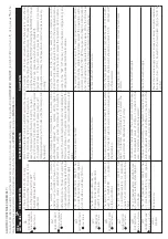


TECHNICAL CHARACTERISTICS.
Power supply voltage
~1x230
Frequency
50/60 Hz
Max. current each phase
10 A (~3 230 V) / 9A (~1 230 V)
Max. peak of current
20% during 10"
Max. operating pressure
15 bar
Max. set pressure
12 bar
Protection index
Ip55
Max. water temperature
40ºC
Max. environment temperature
0-50ºC
Max. flow
15.000 l/h
(1)
There is a 20 A fuse for the INVERTER and another 10 A fuse for the main supply.
HYDRAULIC CONNECTIONS (fig. 2 y 3)
Before proceeding with hydraulic connection it is essential to install a non-return valve in the pump´s inlet.
In case of assembly in group, it must be mounted a collector for the communication of the devices water outputs. The inlet can proceed
from a common or independent origin for each device.
The ZP Speedcontrol Comfort control device must be connected in vertical position (Fig.2), the inlet port ( 1 1/4” male) directly to the
main pump discharge and the outlet port ( 1 1/4” male) at the main network.
If the pump is operating in full aspiration, is strongly recommended to install the external level detector (Fig.8) because the inner flow
sensor of the ZP Speedcontrol Comfort will protect the pump but it will not avoid loss priming in case of dry-running.
ELECTRIC CONNECTION (fig. 4, 5, 6, 7, 8 and 9)
Before doing manipulations inside the device, it should be disconnected of the electric supply and after disabling, wait
for 2 minutes in order to avoid electrical discharges.
Use cables type H07RN-F with section enough to the power installed:
2
Power supply: s
1,5 mm .
2
Motor supply: s
1 mm depending on the cable length (see fig.4).
Verify if the power supply is 220/240 V. Dismount the cover of the electronic circuit and carry out the connections according to the
indications located on the connection strip base.
Do the power supply connection (being sure there is a good earth connection):
L1 N
Do the connection
by mean of magnetothermic
switch in OFF mode.
The earth conductor must be longer than the others. It will be the first one to be mounted during the assembly and the last one The
earth conductor must be longer than the others. It will be the first one to be mounted during the assembly and the last one to
disconnect during disassembling.
Do the pump connection ( Fig. 5, 6 and 7). For the connection of the device to a single-phase motor, the grey cable corresponding to
“U” will not be connected as indicated in 7b diagram (in order to disable the blue cable the rest will be cut until the jacket of the cable
gland and it will be isolated using the insulating tape) - THE INSIDE OF THE DEVICE SHOULD NOT BE MANIPULATED.
Min. level control (optional). There is an input for stopping the pump as soon as is disconnected the external switch of minimum level.
See fig.8.
2
Connection of 2 devices (optional): for the communication of 2 devices it will be used a cable of 4x0.25 mm , it will be inserted throw
the PG cable gland located in the bottom/lateral of the device. See Fig.9.
WARNING!. Wrong connections could spoil the electronic circuit. The manufacturer declines all responsability in damages caused by wrong
connection.
START UP (SINGLE DEVICE).
Be sure that the pump is correctly primed
Connect the ZP Speedcontrol Comfort to the electric supply with the magnetothermic switch, FAILURE led light will be ON. Wait
for 10 seconds
while the ZP Speedcontrol Comfort is doing the autotest. Once it finishes, led light FAILURE is OFF and led light LINE is ON. The LCD
screen will show message “ZP Speedcontrol Comfort ” and inmediately the language display of the configuration mode.
The device is ready for being configured.
START UP (2 DEVICES ASSEMBLY).
If we wish to mount 2 devices for working in groups, previous point should be exactly followed - the order of connection is irrelevant. During
the configuration process we will be able to choose which device is the
MASTER
.
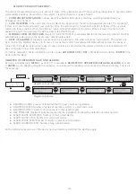
CONFIGURATION OF THE MOTOR SUPPLY (single-phase / three-phases):
The device is suppliedby default for connection to an three-phase motor. If it must be connected to a single-phase motor the following
steps should be followed:
The electrical connection will be done following the indications of the section “ELECTRICAL CONNECTION” for single-phase
motors. (see scheme fig.6).
Once the device is connected, we will press simultaneously the pushbuttons,
MENU
+
ENTER
, to enter in the expert menu. In
this menu can be modified variables of the program (integration, acceleration and deceleration) and also to be chosen the type
of supply of the motor. It is not recommended the modification of the variables.
Values are changed using
p
q
and pushing
ENTER
to memorize changes. Use
ENTER
3 times to confirm the initial values of
the program variables (integration, acceleration and deceleration) and next, using the pushbuttons
p
q
we will choose single-
phase or three-phase. Push
ENTER
to quit the expert menu. Example:
The device must be unswitched from the electric supply and wait until the LCD will be off. Turn on the device again.
± 20% V
INTEGRATION
20
DECELERATION
10
MOTOR
THREE-P U V W
MOTOR
SINGLE-P V W
ACCELERATION
10
q
MENU
ENTER
ENTER
ENTER
ENTER
ENTER
+
-15-
M
M
(1)


