background image

   8 - EN

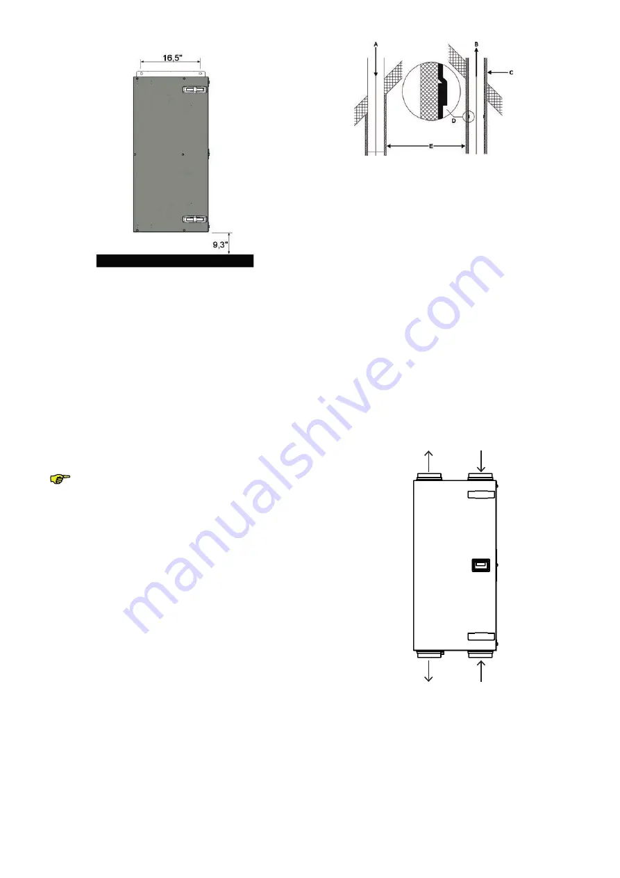
2.6.2  Mounting on the wall 

Mount

 the ComfoAir against a wall with a minimum mass 

of 0.28 lb/in

2

 (200 kg/m

2

).

1.  Using  a  spirit  level,  fix  the  mounting  bracket  hori-

zontally to the wall. Use M8 anchor bolts. Make sure 
there is enough space under the ComfoAir to mount 
the siphon.

2.  Hang the unit in the mounting bracket.
3.  Mount  the  condensation  drain  under  the  ComfoAir. 

The stated dimension of 9.3 inch (235 mm) is an indi-
cation only, and is dependent on the type of conden-
sation drain selected.

Make sure to leave a minimum space of 3.3 feet (1m) in 
front of the ComfoAir for carrying out maintenance.The 
ComfoAir does not require any space at the sides for ef-
fective operation.


Do not mount the side of the ComfoAir against 

the wall due to the risk of impact sound.

2.6.3  Connection of the air ducts

The following aspects must be taken into account, while 
installing the air ducts:

  Install the air exhaust duct so it drains in the direction 

of the ComfoAir.

  Insulate  the  outside  air  supply  and  the  air  exhaust 

duct  between  the  roof/wall  passage  to  render  the 
ComfoAir damp proof. This prevents the formation of 
condensation on the outside of the ducts.

  To  prevent  unnecessary  temperature  loss  in  either 

the summer or the winter, we recommend fitting ther-
mal  and  damp-proof  insulation  to  the  supply  ducts 
from the ComfoAir up to the supply valves.

  Install  the  air  ducts  with  a  minimum  ø  of  4.92  inch 

(125 mm), as little air resistance as possible and free 
from air leakage.

   Install a silencer of at least 3.3 feet (1m) straight di-

rectly onto the supply and return airconnections. For 
relevant advice, please contact Zehnder.

  Do  not  install  a  flexible  air  duct  system.  These  will 

disturb the basic operating principle of the balanced 
ventilation system.

  We  recommend  that  the  ventilation  system  is  fitted 

with intake and exhaust valves made by Zehnder.

Supply air


Return air

Exhaust air


Outside air

ComfoAir 200 - Left

Summary of Contents for ComfoAir 200 Luxe Series

Page 1: ...Cooling Fresh Air Clean Air Heating ComfoAir 200 Luxe Installer manual...

Page 2: ...l has been compiled with the most care The publisher cannot be held liable for any damage caused as a result of missing or incorrect information in this manual In case of disputes the Dutch version of...

Page 3: ...g on the wall 8 2 6 3 Connection of the air ducts 8 2 6 4 Connection of the condensation drain 9 2 7 Commissioning the ComfoAir 9 2 7 2 P menus for the installer 11 2 8 Programming air specifications...

Page 4: ...od of 24 months after fitting up to a maximum of 30 months after the date of manufacture Warranty claims may only be submitted for material faults and or construction faults arising during the warrant...

Page 5: ...not allowed Always take ESD inhibiting measures when deal ing with electronics such as wearing an antistatic wristband The electronics can be damaged by static charges The ComfoAir is only suitable fo...

Page 6: ...th high efficient fan HR High Efficient heat exchanger F Connector panel H2 with connections for external switches and controllers Control panel H1 with connections for the fans the bypass temperature...

Page 7: ...n w c 125 Pa 1 10 A Electricity Power supply 240 50 60 V Hz Cos phi at Maximum 0 8 Connecting Power 1 49 kW Maximum Power Pre heater 1 35 kW Leakage current 1mA Supply fan noise level at 0 m Position...

Page 8: ...Power 1 49 kW Maximum Power Pre heater 1 35 kW Leakage current 1mA Supply fan noise level at 0 m Position Ventilation capacity Sound power Absent Setting 11 77 CFM 20 m3 h at 0 01 in w c 3 Pa 37 db A...

Page 9: ...6 EN 2 3 Dimension sketch...

Page 10: ...is supplied in the following types Type ComfoAir 200 L Luxe ERV ComfoAir 200 R Luxe ERV Meaning of the suffixes L Left version R Right version ERV Contains a enthalpy exchanger by default Luxe Contain...

Page 11: ...ile installing the air ducts Install the air exhaust duct so it drains in the direction of the ComfoAir Insulate the outside air supply and the air exhaust duct between the roof wall passage to render...

Page 12: ...st be commissioned This can be done via the P menus on the digital operat ing device These P menus can be used to enter vari ous settings ventilation programmes in particular for the ComfoAir An overv...

Page 13: ...e input 0 Min 15 Min 0 Min P22 Optional Note Only applies to systems fitted with a corded switch and a second switch in the bathroom Overrun timer for the bathroom switch to switch to normal position...

Page 14: ...city in of the exhaust fan to HIGH POSITION 18 100 nL HL 70 90 P34 Setting the capacity in of the supply fan to ABSENT POSITION 0 or 15 97 nL HL 15 15 P35 Setting the capacity in of the supply fan in...

Page 15: ...type Li Left hand version Re Right hand version Li Re Li With delivery the ComfoAir is correctly pre programmed at the factory After an general reset the pre programming is lost and the setting must b...

Page 16: ...oAir will run at maximum Rotation Per Minute RPM The bypass valve will open and close P77 Resetting filter dirty counter 0 1 activate 0 Note This resets the counter that triggers a dirty filter alert...

Page 17: ...ode the bypass valve is al ways closed After 30 minutes the ComfoAir au tomatically terminates the programming mode 2 Close all windows and outside doors 3 Close all inside doors 4 Check the presence...

Page 18: ...ecessary cleaning the heat ex changer Inspecting and if necessary cleaning the fans A concise explanation of these maintenance activities is given in the paragraphs below Check the condensation drain...

Page 19: ...um of 1 5 Nm This is roughly equal to setting 2 of an average battery powered drill 2 9 2 Inspecting and cleaning the fans Check the fans once every 2 years 1 Remove the heat exchanger as instructed i...

Page 20: ...ription A0 n a A1 NTC sensor T1 is defective outside air temperature A2 NTC sensor T2 is defective supply air temperature A3 NTC sensor T3 is defective return air temperature A4 NTC sensor T4 is defec...

Page 21: ...function Yes No Was the temperature 27 C or 127 C Reset the unit P74 on 1 Disconnect the power from the ComfoAir Disconnect the power from the ComfoAir Disconnect the power from the ComfoAir Release t...

Page 22: ...control circuit board Activate the self test P76 on 1 Did the bypass motor run Yes Disconnect the power from the ComfoAir Replace the control circuit board Remove the motor Disconnect the power from t...

Page 23: ...everse order Reconnect the power to the ComfoAir No Reconnect the power to the ComfoAir Is there 12VDC present on the Luxeconnection panel Yes Disconnect the power from the ComfoAir Replace the Luxe c...

Page 24: ...onnect the power from the ComfoAir Replace the control circuit board Is a control signal 1 5 10 VDC present on the fan Yes No Disconnect the power from the ComfoAir Replace the control circuit board R...

Page 25: ...he ComfoAir Install all parts in reverse order Reconnect the power to the ComfoAir Disconnect the power from the ComfoAir Replace the connection panel Are the connections at the ComfoAir correct Disco...

Page 26: ...panel 2x to reset the FLTR warning Disconnect the power from the ComfoAir Remove the filter caps from the ComfoAir Remove the dirty filters from the ComfoAir Slide the clean new filters back into the...

Page 27: ...o air supply shower remains damp Filters blocked Replace the filters Valves blocked Clean the valves Exchanger clogged by dirt Clean the exchanger Exchanger frozen Defrost the exchanger Fan dirty Clea...

Page 28: ...umber Part Article number 1 Fan Right hand Green 400200034 2 Fan Left hand Red 400200035 3 Control panel 400300051 4 Connector panel 400300031 5 Temperature sensor T1 T3 400300049 6 Temperature sensor...

Page 29: ...26 EN 2 12 Wiring diagram ComfoAir 200 RIGHT HAND version...

Page 30: ...EN 27 2 13 Wiring diagram ComfoAir 200 LEFT HAND version...

Page 31: ...uct ComfoAir 200 UL L R Luxe ERV UL file number E345822 2 15 Temperature conversion table C F C F 5 41 0 23 73 4 6 42 8 24 75 2 7 44 6 25 77 0 8 46 4 26 78 8 9 48 2 27 80 6 10 50 0 28 82 4 11 51 8 29...

Page 32: ...Zehnder America Inc 6 Merrill Industrial Drive Suite 7 Hampton NH 03842 603 601 8544 info zehnderamerica com www zehnderamerica com ZGNL Manual_40011015 V0117 EN Subject to change...

Reviews: