User’s Manual
9
3.
Connect the power supply.
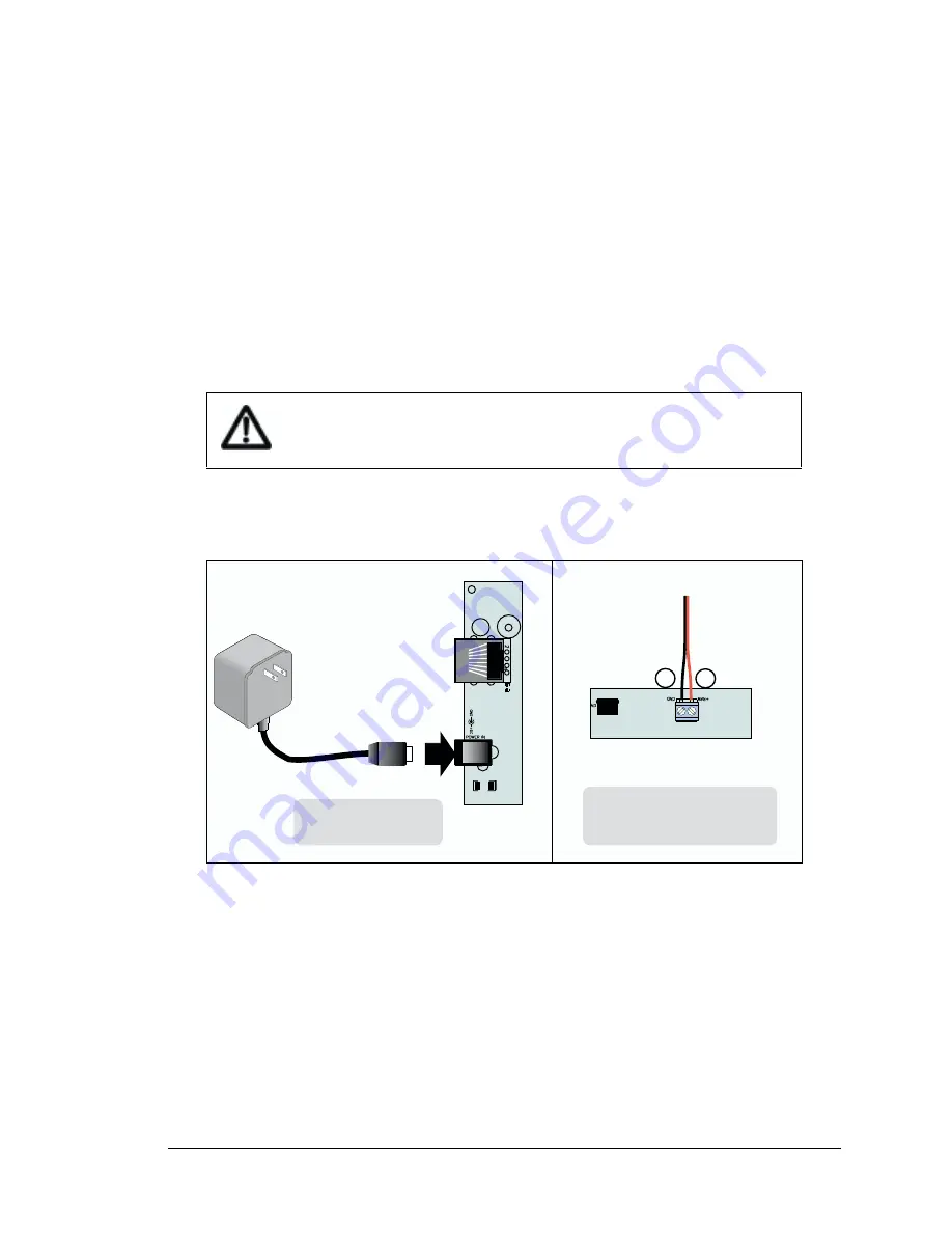
Two options are available for powering the RabbitLink. Option 1 is an AC adapter to power
supply jack J4; option 2 is a screw terminal header at J5. Option 1 is most convenient in a desk-
top environment, and Option 2 can be used to connect the RabbitLink to an existing power sup-
ply in a field installation. The LED labeled USER comes on for several seconds after power is
applied.
Option 1 - Via AC Adapter
Plug the DC end of the power supply into jack J4, which is labeled
POWER IN
, as shown
in Figure 2.1.0-3.
Option 2 - Via Screw Terminal Header J5
Connect the
+
lead (red) to
+RAW
on header J5 and connect the
–
lead (black) to
GND
as
shown in Figure 2.1.0-3.
Figure 2.1.0-3 Alternative Power Supply Connections
NOTE: The RabbitLink (2110) has reverse polarity protection through header J5.
4.
Apply power.
Once the RabbitLink is powered up and connected to your PC, you are ready to configure the
network parameters.
Do not do this hookup if you have already connected the AC adapter
(Option 1).
+
Option 2
Via Screw Terminal
Header J5
Option 1
Via AC Adapter
Summary of Contents for EG2110
Page 22: ...User s Manual 18 ...
Page 26: ...22 RabbitLink EG2110 ...
Page 36: ...32 RabbitLink EG2110 ...
Page 46: ...42 RabbitLink EG2110 ...
Page 48: ...44 RabbitLink EG2110 ...
Page 50: ......


