JOHNSON CONTROLS
141
SECTION 7 - MAINTENANCE
FORM 201.30-ICOM1 (519)
ISSUE DATE: 05/22/2019
7
Improve Dehydration
Circulate hot water (not to exceed 125°F (52°C)
through the evaporator and condenser tubes to thor-
oughly dehydrate the shells. If a source of hot water is
not readily available, use a portable water heater. DO
NOT USE STEAM. A temperature should be brought
up slowly so that the tubes and shell are heated evenly
to avoid causing leaks.
1. Connect a hose between the source of hot wa-
ter under pressure and evaporator head drain
connection.
2. Maneuver the hose out of the evaporator vent con-
nection.
3. Maneuver the hose into the condenser head drain.
4. Maneuver the house out of the condenser vent.
If the system has been pressure tested and found to be
tight prior to evacuation, then the saturation tempera-
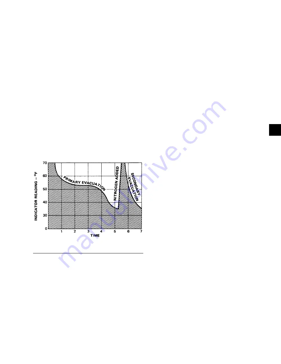
ture recordings should follow a curve similar to the typ-
ical saturation curve as seen in
.
FIGURE 68 -
SATURATION CURVE
LD00474
Remaining System Moisture
The temperature of the water in the chiller will drop
as the pressure decreases, until the boiling point is
reached, at which point the temperature will level off
and remain at this level until all of the water in the
shell is vaporized. When this final vaporization has
taken place the pressure and temperature will continue
to drop until eventually a temperature of 35°F (1.6°C)
or a pressure of 5 mm Hg is reached.
When this point is reached, most of the air has been
evacuated from the system, but there is a small amount
of moisture left. To provide a medium for carrying this
residual moisture to the vacuum pump, introduce nitro-
gen into the system to bring it to atmospheric pressure
and the indicator temperature will return to approxi-
mately ambient temperature. Close off the system again,
and start the second evacuation.
The small amount of moisture left will be carried out
through the vacuum pump and the temperature or pres-
sure shown by the indicator should drop uniformly un-
til it reaches a temperature of 35°F (1.6°C) or a pres-
sure of 5 mm Hg. When the vacuum indicator registers
this temperature or pressure, it is a positive sign that
the system is evacuated and dehydrated to the recom-
mended limit. If this level cannot be reached, there is
a leak somewhere in the system, which must be cor-
rected before the indicator can be pulled down to 35°F
(1.6°C) or 5 mm Hg in the primary evacuation.
During the primary pulldown, carefully watch the wet
bulb indicator temperature, and do not let it fall below
35°F (1.6°C). If the temperature is allowed to fall to
32°F (0°C), the water in the test tube will freeze, and
the result will be a faulty temperature reading.
Vacuum Testing
After completing the pressure test, the vacuum test
should be conducted as follows:
1. Connect a high capacity vacuum pump, with indi-
cator, to the system charging valve or shell service
valve and start the pump. Refer to
Dehydration of Unit on page 140
2. Open wide all system valves, including the purge
and gauge valves. Be sure all valves to the atmo-
sphere are closed.
3. Operate the vacuum pump in accordance with
Vacuum Dehydration
until a wet bulb tempera-
ture of 32°F (0°C) or a pressure of 5 mm Hg is
reached. Refer to
STORAGE, INSTALLATION AND REASSEMBLY
for corresponding values of pressure.
4. Close the system charging valve and the stop valve
between the vacuum indicator and the vacuum
pump, then disconnect the vacuum pump leaving
the vacuum indicator in place.
5. Hold the vacuum wet bulb temperature obtained
in Step 3 in the system for eight hours; the slight-
est rise in pressure indicates a leak or the presence
of moisture, or both. If, after eight hours the wet
bulb temperature in the vacuum indicator has not
risen above 40°F (4.4°C) or a pressure of 6.3 mm
Hg, the system may be considered tight.
Summary of Contents for YVWA
Page 155: ...JOHNSON CONTROLS 155 NOTES...


