


JOHNSON CONTROLS
34
FORM 160.67-O1
ISSUE DATE: 4/1/2015
SECTION 2 - OPTIVIEW CONTROL CENTER INTRODUCTION
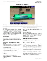
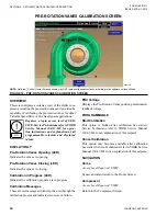
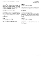
proxiMiTY probe CalibraTion SCreen
00305VIP
figure 11 - proxiMiTY probe CalibraTion SCreen
noTe:
OptiView
™
Control Center Screens shown may NOT represent the exact screens according to the software version utilized.
overvieW
This screen displays a cutaway view of the chiller com-
pressor, revealing the proximity probe sensor and pro-
vides the capability of calibrating the proximity probe
sensor. It is only displayed when the "Compressor
Thrust Probe" is set for "Position" on the Operations
Screen.
Requires a login access for operation
instructions and explanation of all
programmable setpoints and displayed
values.
diSplaY onlY
high Speed Thrust bearing proximity
position
Displays the distance between the high-speed thrust
collar and the proximity probe that is used to measure
the position.
high Speed Thrust bearing proximity
reference position
Displays the presently defined offset reference posi-
tion. This value is defined at the conclusion of a cali-
bration sequence.
oil pressure
Displays the pressure differential between the high
side oil pressure transducer (compressor bearing input)
and the low side oil pressure transducer (oil sump). The
displayed value includes offset pressure derived from
auto-zeroing during the system prelube. If either of the
transducers used to calculate this differential is out of
range, the display field will show XX.X.
Calibration in progress (led)
Indicates that the calibration sequence is in progress.
Calibration Messages
These are text messages which step the user through
the calibration process and indicate its success or fail-
ure.
prograMMable
enter reference
Start Calibration
This option is hidden after calibration has started.
Cancel Calibration
This option only becomes available after calibration
has started.
Summary of Contents for YST
Page 163: ...JOHNSON CONTROLS 163 NOTES...


