


FORM NO.:6U6K-B01E-NB-EN
JOHNSON CONTROLS
100
MODE SETTING
Δp-c/Δp-v control:
Manual control mode:
“Manual control” mode deactivates all other control modes.
The speed of the pump is kept to a constant value and set using
the rotary knob.
The speed range is dependent on the motor and pump type.
PID control:
The PID controller in the pump is a standard PID controller,
as described in control technology literature. The controller
compares a measured process value to a predefined setpoint and
attempts to adjust the process value to match the setpoint as
closely as possible.
Provided appropriate sensors are used, a variety of control
systems (including pressure, differential pressure, temperature
and flow control) can be realized.
The control behavior can be optimized by adjusting the P, I and
D parameters. The P (or proportional) term of the controller
contributes a linear gain of the deviation between the process
(actual) value and the setpoint to the controller output. The sign
of the P term determines the controller's direction of action.
The I (or integral) term of the controller provides integral
control based on the system deviation. A constant deviation
results in a linear increase at the controller output. Hence a
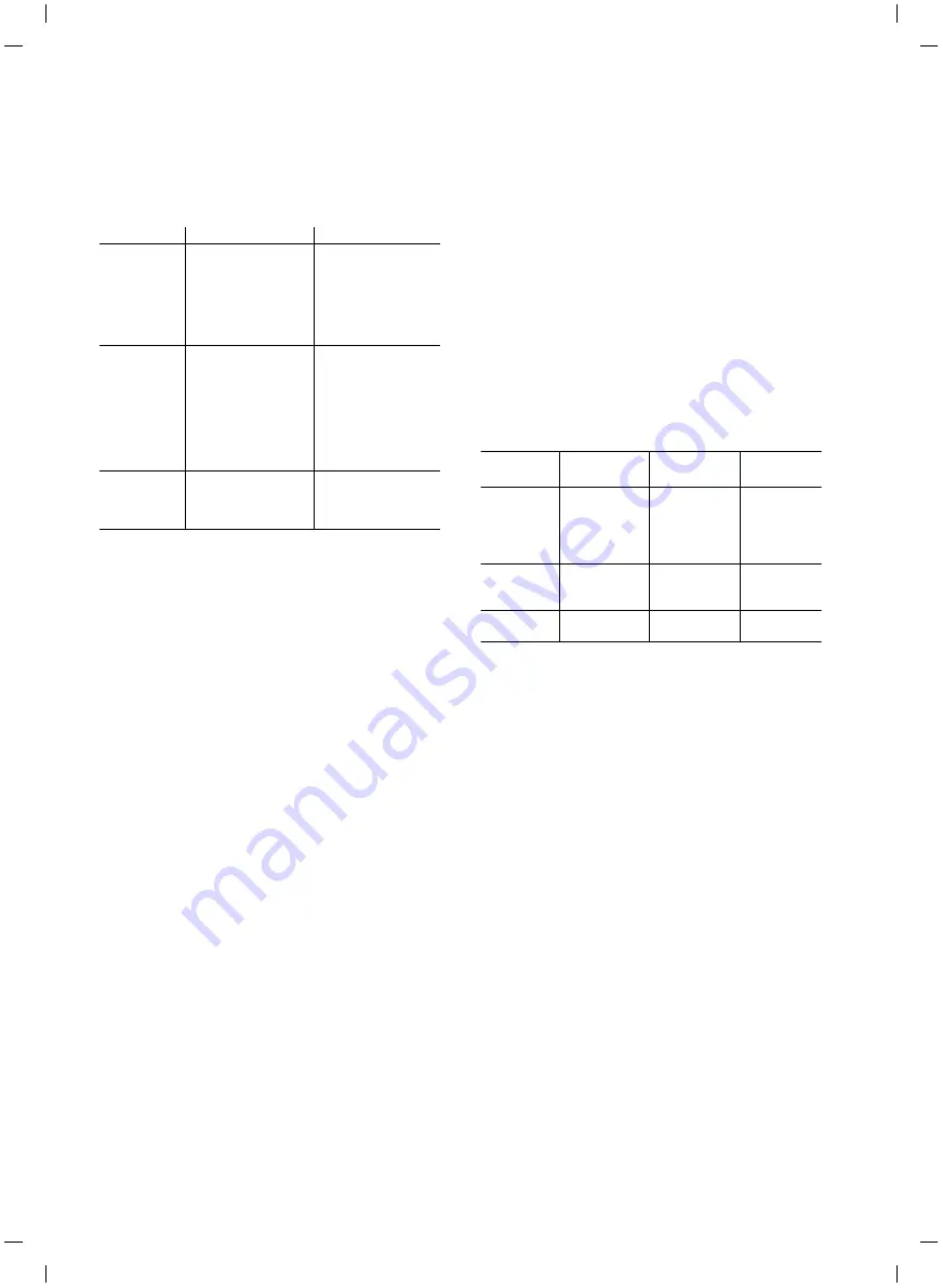
Setting
Δ
p-c
Δ
p-v
Duty point on
maximum
pump curve
Starting at the duty
point, draw towards
the left. Read off
setpoint HS and set
the pump to this
value.
Starting at the duty
point, draw towards
the left. Read off
setpoint HS and set
the pump to this
value.
Duty point
within the
control range
Starting at the duty
point, draw towards
the left. Read off
setpoint HS and set
the pump to this
value.
Move to max. pump
curve along control
curve, then
horizontally to the
left, read off
setpoint HS and set
the pump to this
value.
Setting range
Hmin, Hmax
See pump curves
(e.g. on data sheet)
Hmin, Hmax
See pump curves
(e.g. on data sheet)
continuous system deviation is avoided.
The D (or derivative) term responds directly to the rate of
change of the system deviation. This affects the rate at which
the system responds. In the factory settings, the D term is set
to zero, since this is an appropriate setting for a number of
applications.
These parameters should only be changed in small increments,
and the effects on the system should be monitored continuously.
Parameter values should only be tuned by someone with
training in control technology.
The direction of action of the controller is determined by the
sign of the P term.
Positive PID control (default):
If the sign of the P term is positive and the process value drops
below the setpoint, the control will increase the pump speed
until the setpoint has been reached.
Negative PID control:
If the sign of the P term is negative and the process value drops
below the setpoint, the control will decrease the pump speed
until the setpoint has been reached.
NOTE:
Check the controller's direction of action if PID control is being
used, but the pump is only running at minimum or maximum
speed without responding to changes in the parameter values.
DISPLAY
Information appears on the display as shown in the sample
illustration below:
Controller
term
Factory
setting
Setting
range
Increment
P
0.5
-30.0 ~ -2.0
-1.99 ~ -
0.01
0.00 ~ 1.99
2.0 ~ 30.0
0.1
0.01
0.01
0.1
I
0.5 s
10 ~ 990
ms
1 ~ 300 s
10 ms
1 s
D
0 s (=
deactivated)
0 ~ 990 ms
1 ~ 300 s
10 ms
1 s
SECTION 6 – COMMISSIONING
Cooke Industries - Phone: +64 9 579 2185 Email: [email protected] Web: www.cookeindustries.co.nz


