


4-4
EN
Form 6S6I-B01C-EOMA-EN (0318)
Piping Connections
The following connection recommendations are
intended to ensure safe and satisfactory operation of
the unit. Failure to follow these recommendations could
cause harm to persons, or damage to the unit, and may
invalidate the warranty.
The maximum flow rate and pressure drop for
the evaporator and condenser must not be
exceeded at any time. Refer to Section 9 for
details.
A flow switch must be directly in series with the
evaporator/ condenser and wired back to the control
panel using screened cable. For details, refer to
customer connection diagram. This is to prevent
damage to the evaporator/ condenser caused by
inadequate liquid flow. A paddle type flow switches are
suitable for 10 bar working pressure.
The chilled water pump should be installed in the
entering water pipe. Pipework and fittings must be
separately supported to prevent any loading on the
unit. Flexible connections are recommended which will
also minimize transmission of vibrations to the building.
Flexible connections must be used if the unit is mounted
on anti-vibration mounts as some movement of the unit
can be expected in normal operation.
Pipework and fittings immediately next to the evaporator
should be readily dismantled to enable cleaning prior to
operation, and to facilitate visual inspection of the heat
exchanger nozzles.
A strainer must be mounted on the waterside of the
evaporator and condenser respectively, preferably of
40 mesh, fitted as close as possible to the liquid inlet
connection, and provided with a local water cut-off
switch.
The evaporator must not be exposed to too high
flushing velocities or debris deposited during flushing.
It is recommended that a suitably sized by-pass
and valve arrangement be installed to allow flushing
of the pipework system. The by-pass can be used
during maintenance to isolate the evaporator without
disrupting flow to other units.
Thermometer and pressure gauge connections should
be provided on the inlet and outlet connections of the
evaporator and condenser.
Drain and vent valves (by others) should be installed in
the connections provided in the cooler and condenser
liquid heads. These connections may be piped to drain
if desired.
Any debris left in the water piping between
the strainer and cooler could cause serious
damage to the tubes in the cooler and must
be avoided. The installer/user must also
ensure that the quality of the water in
circulation is adequate, without any dissolved
gases, which can cause oxidation of steel
parts within the cooler.
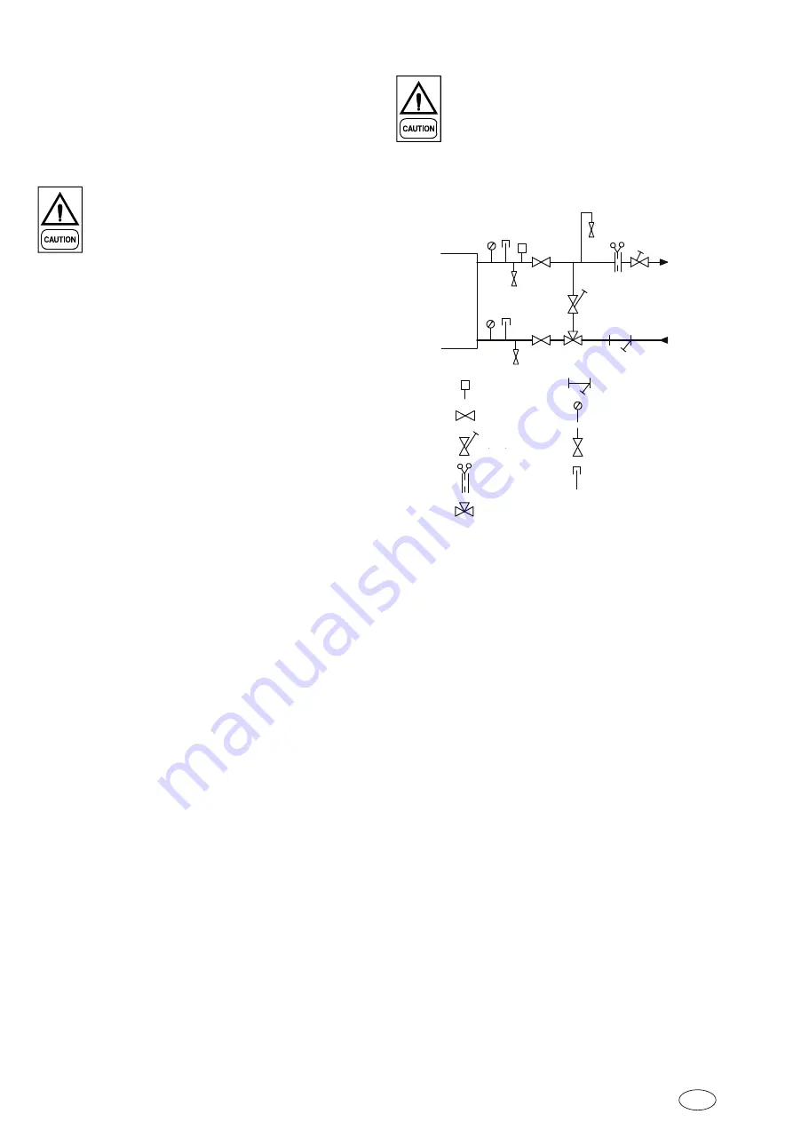
Evaporator
or
Condenser
Flow Switch
Stop Valve
Regulation
Valve
Flow Meter
Filter
Pressure Meter
Drain
Thermometer
3-way Valve for Flow Rate Control
Water Treatment
The unit performance provided in the design guide
is based on a fouling factor of (0.044 m²/KW for
condenser and 0.0018 m²/KW for evaporator). Dirt,
scale, grease and certain types of water treatment
will adversely affect the heat exchanger surfaces and
therefore the unit performance. Foreign matter in the
water system(s) can increase the heat exchanger
pressure drop, reducing the flow rate and causing
potential damage to the heat exchanger tubes. YORK
recommends that a water treatment specialist should
be consulted to determine whether the proposed
water composition will adversely affect the evaporator
materials of carbon steel and copper. The pH value of
the water flowing through the evaporator must be kept
in a range between 6.5 and 8.0. The water quality of
chiller should be in accordance with local code.
Summary of Contents for YGWH 115
Page 2: ......
Page 10: ...1 6 EN Form 6S6I B01C EOMA EN 0318 Page Left Intentionally Blank...
Page 24: ...4 8 EN Form 6S6I B01C EOMA EN 0318 Customer Connections...
Page 40: ...6 14 EN Form 6S6I B01C EOMA EN 0318 Page Left Intentionally Blank...
Page 58: ...10 2 EN Form 6S6I B01C EOMA EN 0318 Page Left Intentionally Blank...


