background image

YORK INTERNATIONAL

94

FORM 201.25-NM1 (302)

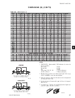
TABLE 20 – 

MOUNTING DIMENSIONS (INCHES)

 MODEL

AA

BB

CC

YCRS0100SC

115-5/8

34

23-3/4

YCRS0120SC

115-5/8

34

23-3/4

YCRS0140SC

115-5/8

34

23-3/4

YCRS0180SC

162-7/8

36

25-3/4

YCRS0200SC

162-7/8

36

25-3/4

YCRS0220SC

162-7/8

36

25-3/4

YCRS0240SC

162-7/8

36

25-3/4

DIMENSIONS (ENGLISH)

Technical Data

CONNECTION

LIQUID INLET

S


COOLER

VICTAULIC

SYSTEM
 # 1

SYSTEM
 # 2

CONNECTION

S
COOLER
LIQUID OUTLET
VICTAULIC

RELIEF
VALVE
300 PSI
EACH
SYSTEM

CG

Z

X

ORIGIN

B

D

C

F

CL

G

H

I

E

A

XL1

XL2

ZD1

XD1

XD2

SYS. 2
1-1/8" O.D.
LIQ. CONN.

SYS. 1
1-1/8" O.D.
LIQ. CONN.

SYS. 1
1-5/8" O.D.
DISCH. CONN.

SYS. 2
1-5/8" O.D.
DISCH. CONN.

ZD1

G

C

Y

X

ORIGIN

10-1/4"

BB

CC

6-3/8"

3-3/8"

AA

5-1/8"

4 HOLES Ø3/4" FOR
MOUNTING BOLTS

VIEW SHOWING MOUNTING LOCATIONS

M

X TO RIGGING HOLE

HOLES

RIGGING

Ø1 1/2"

L

P

Q

O

N

K

J

R TO COOLER CONN.

C

L

SYS. 1&2
LIQ. CONNS.

YD1 & YD2

ZL1

SYS. 1&2
DISCH. CONNS.

YL1

TABLE 21 –

 CENTER OF GRAVITY (INCHES)

 MODEL

X

Y

        Z

YCRS0100SC

57

21

39

YCRS0120SC

58

22

39

YCRS0140SC

57

22

39

YCRS0180SC

80

24

43

YCRS0200SC

80

24

43

YCRS0220SC

80

24

43

YCRS0240SC

80

24

43

LD07759

LD07760

LD07761

Summary of Contents for YCRS Series

Page 1: ... MAINTENANCE YCRS WATER COOLED LIQUID CHILLERS New Release Form 201 25 NM1 302 60 HERTZ STYLE A REFRIGERANT TYPE R 22 YCRS WATER COOLED REMOTE CONDENSER YCRS0100SC 0240SC 81 TONS THROUGH 194 TONS 285 KW THROUGH 682 KW 00635VIP ...

Page 2: ...YORK INTERNATIONAL 2 FORM 201 25 NM1 302 ...

Page 3: ...ies 15 Aternative Chilled Fluid Applications 15 Nomenclature 16 Functional Description 16 SECTION 3 TRANSPORTATION HANDLING AND STORAGE Delivery and Storage 17 Inspection 17 MovingtheUnit 17 Lifting by Crane Hoist 17 Lifting by Fork Lift 18 ControlPanelRemoval 18 Lifting Weights 18 SECTION 4 INSTALLATION Location Requirements 19 Installation of Vibration Isolators 19 Pipework Connection 19 General...

Page 4: ...STATUSKEYS 40 3 1 General 40 3 2 General Status Messages 40 3 3 Unit Warnings 41 3 4 Anticipation Control Status Messages 42 3 5 Unit Fault Status Messages 43 3 6 System Fault Status Messages 44 3 7 Printout on Fault Shutdown 47 4 DISPLAYKEYS 48 4 1 General 48 4 2 Chilled Liquid Temps Key 48 4 3 System Data Keys 48 4 4 Ambient Temp Key 49 4 5 Motor Current Key 49 4 6 Operating Hrs Start Counter Ke...

Page 5: ...75 StandardUnits 77 Troubleshooting Guide 78 Sensor Calibration Charts 80 Typical Control Panel Wiring 82 SECTION 9 TECHNICALDATA Flow Rate and Pressure Drop Graphs 84 Physical Data Sound Data 87 Electrical Data 88 Dimensions 94 Isolator Selection Data 98 Isolator Details 99 SoundData 100 Compressors 101 SECTION 10 SPARE PARTS Recommended Spare Parts 102 Recommended Compressor Oils 102 Associated ...

Page 6: ... must be supported by evidence that the failure has occurred within the warranty period and that the unit has been operated within the designed parameters specified All warranty claims must specify the unit model serial number order number and run hours starts These de tails are printed on the unit identification plate The unit warranty will be void if any modification to the unit is carried out w...

Page 7: ...and is not suitable for purposes other than those specified in these instructions Any use of the equipment other than its intended use or operation of the equipment contrary to the relevant procedures may result in injury to the op erator or damage to the equipment The unit must not be operated outside the design pa rameters specified in this manual Structural Support Structural support of the uni...

Page 8: ...in confined or enclosed spaces and attention should be given to good ventilation High Temperature and Pressure Cleaning High temperature and pressure cleaning methods e g steam cleaning should not be used on any part of the pressure system as this may cause operation of the pres sure relief device s Detergents and solvents which may cause corrosion should also be avoided EMERGENCY SHUTDOWN In case...

Page 9: ...wo helically grooved rotors which are manufactured from forged steel The 60 Hz motor operates at 3600 rpm to direct drive the male rotor which in turn drives the female rotor on a light film of oil Each compressor is direct drive semi hermetic rotary twin screw type and includes the following items Two screw rotors with asymmetric profiles manufac tured from forged steel A cast iron compressor hou...

Page 10: ...ant condensation Motor Starting Compressor motor starting is Star Delta S D open transition The starter utilizes 3 motor contactors a tran sition delay relay and a start relay The starter allows inrush current to be limited to approximately 33 LRA for the first 4 to 10 seconds with current increasing to normal running current when the Delta connection is completed When the microprocessor initiates...

Page 11: ...sure protection of the compressor Oil pressure is measured as the difference between dis charge pressure and the pressure of the oil entering the rotor case Maximum working pressure of the oil separator is 31 bar 450 psi The oil level should be above the mid point of the lower oil sight glass when the compres sor is running The oil level should never be above the top of the upper sight glass Oil t...

Page 12: ...re is stored in non volatile memory EPROM to eliminate unit failure due to AC power failure The programmed setpoint is stored in a lithium battery backed memory MOTOR CURRENT PROTECTION The microprocessor motor protection provides high cur rent protection to assure that the motor is not damaged due to voltage excess refrigerant or other problems that could cause excessive motor current If the moto...

Page 13: ...nual after the motor cools and the sensor resistance drops to 3 25 kW Current Unbalance Loaded Unloaded Loss of Phase A 2 second delay at start up allows for any unbalances resulting during normal starting conditions After this initial delay the protector module compares the Op erating Current to the measured half line current The Operating Current is given by 0 65 x factory over load current sett...

Page 14: ...inal Blocks Two field supplied elec trical power circuits with appropriate branch circuit pro tection provide power to each of two motor control cen ter cabinets located on either side of the Control panel on the front of the chiller Each cabinet contains starter elements for one compressor Optional to the Terminal Blocks for field power con nection are Non Fused Disconnects or Circuit Breaker Swi...

Page 15: ...ry VIBRATION ISOLATION Neoprene Isolators Recommended for normal installations Providesverygoodperformanceinmost applications for the least cost Field mounted 1 Spring Isolators Level adjustable spring and cage type isolators for mounting under the unit base rails 1 nominal deflection may vary slightly by application Field mounted 2 Seismic Spring Isolators Restrained Spring Flex Mountings incorpo...

Page 16: ...tilizes a refrigerant to refrigerant suction line heat exchanger to maximize chiller capacity andefficiencybysubcoolingliquidrefrigerantdeliveredto the expansion valve and superheating suction gas deliv ered to the compressor FIG 3 FLOW DIAGRAM Product Description YCRS0140SC46YAA Design Series F Engineering Change or PIN Level YORK Chiller Remote Condenser kW Standard Unit 0100 0120 0140 0180 0200...

Page 17: ...d during storage INSPECTION Remove any transit packing and inspect the unit to en sure that all components have been delivered and that no damage has occurred during transit If any damage is evident it should be noted on the shipment docu mentation and a claim entered according to the instruc tions given Major damage must be reported immediately to your local YORK representative MOVING THE UNIT Be...

Page 18: ... lifting slots on both sides of the unit to prevent damage CONTROL PANEL REMOVAL For installation in locations where access width is lim ited the control panel may be removed as shown in the figure below FIG 5 CONTROL PANEL REMOVAL LIFTING WEIGHTS For details of weights and weight distribution refer to Section 9 Transportation Handling and Storage LD06595 ...

Page 19: ...solated from walls and ceiling The unit may be bolted to the foundation using 1 2 13 mm Ø holes in the base of the framework When lower transmitted vibration levels are required optional anti vibration isolators can be supplied loose for site installation INSTALLATION OF VIBRATION ISOLATORS An optional set of vibration isolators can be supplied loose with each unit refer to Section 9 for details P...

Page 20: ...eater tape of 21 watts per meter un der the insulation is recommended supplied independently and controlled by an ambient temperature thermostat set to switch on at 37 F 3 C above the freezing temperature of the liquid Any debris left in the water pipework between the strainer and heat ex changer could cause serious damage to the tubes in the heat exchanger and must be avoided The installer user m...

Page 21: ... 8 1 32 3 8 1 32 5 395 TABLE 2 CONDENSER COOLER CONNECTIONS 4 PIPEWORK ARRANGEMENT The following are suggested pipework arrangements for single unit installations For multiple unit installa tions each unit should be piped as shown Recommendations of the Building Services Research Association CONNECTION TYPES SIZES For connection sizes relevant to individual models re fer to Section 9 Cooler Connec...

Page 22: ...he power to capacity ratio kW ton of the system and decreases the compressor capacity This is illustrated in Figure 11 ASHRAE recommends a saturation temperature change of 1 F based on frictional pressure drop for dis charge line sizing Table 3 contains discharge line sizing data for refrigerant R22 Capacities are for a condens ing temperature of 105 F and correction factors are given at the botto...

Page 23: ... 80 21 1 55 4 1 1 2 40 19 0 19 7 20 3 21 0 21 5 1 1 2 80 29 1 84 5 2 40 36 6 37 9 39 2 40 4 41 5 2 40 55 3 196 5 2 1 2 40 58 3 60 4 62 5 64 3 66 1 2 1 2 40 78 9 313 4 3 40 103 0 106 7 110 3 113 6 116 7 3 40 121 8 554 0 4 40 209 6 217 3 224 5 231 3 237 5 4 40 209 8 1129 0 5 40 378 3 392 1 405 2 417 4 428 6 5 40 329 7 2039 0 6 40 611 1 633 3 654 4 674 1 692 3 6 40 476 2 3294 0 Capacities are in tons...

Page 24: ...s and the power supply terminals on the unit To ensure that no eddy currents are set up in the metal gland plate the cables forming each 3 phase power sup ply must enter via the same hole in the gland plate If separate entries for each cable forming the 3 phase supplies are used the metal gland plate must be re placed by a non metallic gland plate with due regard given to sealing the panel to NEMA...

Page 25: ...be connected to terminals 24 and 13 to provide adequate protection against loss of liquid flow Control Transformer Primary Voltage Tappings It is important to check that the correct primary tapping has been used on the control transformer With the supply to the unit isolated remove the lid to the transformer box Check that the tapping used conforms to the site supply voltage The two tappings are 3...

Page 26: ...ing Data Fault History to be obtained an optional printer must be connected to the RS 232 port on the micropro cessor board Remote Setpoint Offset Temperature PWMT Timed closure of suitable contacts connected to termi nals 27 and 13 PWM contacts will give remote offset function of the chilled liquid setpoint if required Remote Setpoint Offset Current PWMC Timed contact closure of a suitable contac...

Page 27: ... 302 27 YORK INTERNATIONAL FIG 12 MULTI POINT POWER SUPPLY CONNECTION STANDARD UNIT FIG 13 SINGLE POINT POWER SUPPLY WITH INTERNAL CIRCUIT BREAKER OR NON FUSED DISCONNECT SWITCH CUSTOMER WIRING DATA LD07155 LD07156 4 ...

Page 28: ...MUM CIRCUIT AMPACITY MIN MINIMUM MIN NF MINIMUM NON FUSED RLA RATED LOAD AMPS Y D LRA WYE DELTA INRUSH LOCKED ROTOR AMPS VOLTAGE CODE 17 200 3 60 28 230 3 60 40 380 3 60 46 460 3 60 58 575 3 60 NOTES 1 Dashed line indicates field provided wiring 2 The above recommendations are based upon the National Electric Code and the use of copper connectors only Field wiring must comply with local codes 3 Si...

Page 29: ...n Section 9 Valves Open the compressor suction and discharge and liquid line service valves on both systems Compressor oil The compressor oil level must be between the two sight glasses on the oil separators Isolation protection Verify that all sources of electri cal supply to the unit are taken from point s of isola tion Control panel Check the panel to see that it is free of foreign materials wi...

Page 30: ... within the lim its given in Section 9 Switch Settings Ensure that the unit ON OFF toggle switch on the control panel and the microprocessor board system switches S2 and S3 are set to OFF Set the red emergency stop device on the common in put section to 1 ON For units fitted with door in terlocked isolators the power section doors must be closed and the devices set to 1 ON The customers disconnect...

Page 31: ...requires the unit to run or is overridden System switches Set the system 1 switch on the mi croprocessor board to the ON position see operat ing sequence in the MBCS Section Start up Press the STATUS key and set the toggle switch to the ON position to start the unit there may be a few seconds delay before the first compressor starts because of the anti recycle timer Be ready when each compressor s...

Page 32: ...ill start The display will show the anti coincidence timer status for the lag compressor NORMAL RUNNING AND CYCLING Once the unit has been started all operations are fully automatic After an initial period at minimum capacity on the lead compressor the control system will adjust the unit load depending on the chilled liquid tempera ture and rate of temperature change If high heat load is present t...

Page 33: ...nverts 24VAC from the logic transformer 2T to 12VDC REG which is supplied to the AMB board ARB boards and the 40 character display to operate the integrated circuitry The 24VAC is filtered but not regu lated to provide unregulated 24VDC to supply the flow switch PWM remote temperature reset PWM re mote current reset lead lag select and remote print cir cuitry which may be utilized with user suppli...

Page 34: ... send an analogue sig nal proportional to average motor current to AIOB board and on to the AMB board for microprocessor low high current protection and current display This allows the microprocessor to monitor current and shut a system down if low or high motor current is sensed This is a non adjustable protection circuit electronically sized to a system s motor specifications Internally the onbo...

Page 35: ...t flow switch to terminal 13 to feed the two start stop con tacts Then connect No 1 system start stop contact to terminal 24 and No 2 system start stop contact to ter minal 25 With the associated contact open the NO RUN PERM message will be displayed and the asso ciated systems will not run 1 12 REMOTE CURRENT RESET The maximum allowable running current for each com pressor can be adjusted remotel...

Page 36: ...ise immunity the micropro cessor will ignore closures of less than 1 second To calculate the necessary contact closure time to pro vide a required Reset use the following steps RESET TEMPERATURE CONTACTCLOSURE 1SEC XPROGRAMMEDMAXRESET OFFSET 10 SEC For example with a programmed setpoint of 44 F 7 C after a 4 second pulse and a programmed maximum offset of 40 F 22 C the temperature offset would equ...

Page 37: ... N E C it is recommended that the customer wiring to these terminals uses orange wires This will ensure that circuits not switched off by the units supply disconnect ing device are distinguished by color so that they can easily be identified as live even when the unit discon necting devices are off The YORK voltage free con tacts are rated at 125VA All inductive devices relays switched by the YORK...

Page 38: ...noid valve are de energized The compressor continues to operate until it either pumps down to the low suction pressure cutout setting or for 180 seconds whichever comes first Pump down occurs on normal shutdowns where cool ing demand has been satisfied or when a system switch is turned off a flow switch opens run permissive is lost or a Daily Schedule or a remote shutdown is called for No pump dow...

Page 39: ...h This switch shuts down the entire chiller when placed in the OFF position The switch must be ON for the chiller to operate 2 2 PROGRAM AND SETUP KEYS Entry Keys refer to Section 6 The numeric and associated keys are used for entering data required for programming the chiller The EN TER and keys are also used for scrolling through information available after pressing certain keys Setpoints Keys r...

Page 40: ...SSAGES Unit Switch OFF The unit ON OFF switch on the control panel is in the OFF position and the chiller will not run Schedule Shutdown The chiller has been shut down by the DAILY SCHED ULE programmed into the CLOCK Remote Controlled Shutdown The ISN or RCC Remote Control Center has turned the unit OFF through the RS 485 port Compressor Running The respective compressor is running due to demand S...

Page 41: ...nt where the microprocessor will bring the lead system on and or that the loading sequence has not loaded the chiller far enough to bring the lag system on The lag system will display this message until the load ing sequence is ready for the lag system to start 3 3 UNIT WARNINGS Unit warnings indicate conditions which require op erator intervention to start the unit or extreme operat ing condition...

Page 42: ...discharge pressure has ex ceeded the programmable threshold and the compres sor is being unloaded to prevent nuisance shutdown on the high pressure cutout The operation of this safety is important if condenser coils become dirty if there is a problem with the con denser fan operation or if extreme ambient or load con ditions occur Compressor Motor Current Limiting The message indicates that a comp...

Page 43: ... in ambi ents above 130 F 54 C where potential malfunction of system mechanical and electrical components may result The cutout is programmable and can be set for lower limit values if required The fault will clear when ambient temperature drops 30 F 1 C below the cutout Low Leaving Chilled Liquid Temperature Cutout This cutout assures that the evaporator is not damaged from freezing due to improp...

Page 44: ... cutout protects the compressor rotors from dam age due to overheating expansion and breakdown of the oil film seal between the rotors It also protects against excessive oil temperature in the discharge oil separator For the first 4 seconds of operation discharge tempera ture is ignored After 4 seconds of operation the com pressor will shutdown if the discharge temperature ex ceeds 260 F 127 C Hig...

Page 45: ...nored for the first 45 seconds of operation During the next 180 seconds of running suction pressure may be lower than the cutout but must be greater than SUCTION PRESSURE PROGRAMMED CUTOUT RUN TIME 25 CUTOUT 25 This cutout value increases with time until after 225 sec onds it equals the programmed cutout value If suction pressure falls below the calculated cutout value before 225 seconds of run ti...

Page 46: ...is not pumping due to a mechanical mal function Motor current is monitored using 3 current transformers CTs per motor one on each phase Average motor current is monitored after 3 seconds of compressor operation From this time the system will be shutdown if average motor current is less than 10 of FLA Compressor motor protection modules and mechani cal high pressure cutouts are fitted to each syste...

Page 47: ... of History Buffer 1 will be sent to the printer any time a fault shutdown occurs This will allow record keeping of individual faults even if they do not cause a lock out of the system This in formation may be useful to identify developing prob lems and troubleshooting The NO RUN PERMISSIVE fault messages will not be stored in the History Buffer and will not cause an automatic printout Due to extr...

Page 48: ...d but are outside the ability of the microprocessor to give an actual read ing This is unlikely to occur unless a problem exists in the measuring sensors or during extreme conditions The display keys and the data available from each is as follows 4 2 CHILLED LIQUID TEMPS KEY When the key is pressed the chiller leaving chilled liq uid temperature LCHLT and returning chilled liquid temperature RCHLT...

Page 49: ... Limits Minimum 4 6 F 20 3 C Maximum 137 9 F 58 8 C 4 5 MOTOR CURRENT KEY Pressing the key displays compressor current for each system This display shows the average motor current in amps and average compressor motor current as a percentage of FLA All values are approximate On the second press of the of the key the current limit values as set by the ISN Remote BAS System and EMS PWM current limiti...

Page 50: ... key is pressed SWITCH 1 Water Brine Cooling Open Water cooling mode is for water cooling applications and allows the chilled liquid leaving temperature set point to be programmed from 40 70 F 4 4 to 21 1 C Selecting this mode also auto programs the low chilled liquid cutout at 36 F 2 2 C and the suction pressure cutout at 44 psi 3 03 bar Closed Brine cooling mode is for brine glycol applications ...

Page 51: ... shown below without the need to press the SYSTEM 1 DATA key to scroll to the next display After scrolling through the data the display returns to the status message The FUNCTION Key can be used to scroll through the displays for Chilled Liquid Temps System Data Motor Current Options FIG 16 ENLARGED PHOTOGRAPH OF DIP SWITCHES ON MICROPROCESSOR BOARD LD03511A LD03511B OPEN Position Left side of swi...

Page 52: ...itted it is erased from the memory Information available using the OPER DATA key is de scribed in the following sections In example displays is used to indicate system number where appropriate 5 3 OPER DATA LOCAL DISPLAY MESSAGES When the OPER DATA key is pressed the following message appears Repetitively pressing the keys will scroll through the common whole chiller data and individual sys tem da...

Page 53: ...nly relevant if the unit is controlling a re mote air cooled condenser and the status of the com pressor heater Once the system data sequence has been repeated for the other systems pressing the o r keys again will loop back to the beginning to the common data To exit the sequence at any point press a key from an other section of the keypad Pressing the at any time while in the operating data mode...

Page 54: ... 0 00 00 D H M S MOTOR CURRENT 0 AMPS 00 FLA SUCTION PRESSURE 125 PSIG DISCHARGE PRESSURE 131 PSIG OIL PRESSURE 130 PSIG SUCTION TEMPERATURE 68 4 DEGF DISCHARGE TEMPERATURE 71 8 DEGF OIL TEMPERATURE 3 4 DEGF SAT SUCTION TEMP 74 5 DEGF SUCTION SUPERHEAT 6 3 DEGF SAT DISCHARGE TEMP 74 5 DEGF DISCHARGE SUPERHEAT 6 3 DEGF SLIDE VALVE STEP 0 COOLER INLET REFRIG 44 6 DEGF LIQUID LINE SOLENOID OFF OIL CO...

Page 55: ...L DISPLAY MESSAGES When the HISTORY key is pressed the following message will appear To select a Safety Shutdown press the appropriate key on the numeric key pad then press ENTER Remem ber that the most recent fault information is stored as shutdown No 1 After the ENTER Key is pressed a message indicat ing the time and date of the Fault Shutdown will appear D I S P L A Y S A F E T Y S H U T D O W ...

Page 56: ...message indicates that a remote device such as a Remote Control Center an ISN controller or another device sending a PWM signal for temperature or cur rent reset is overriding control points programmed through the keypad or default microprocessor setpoints System Data Following the common data is a sequence of system messages which are repeated for each refrigerant sys tem These messages display s...

Page 57: ...I G S Y S O I L 1 3 1 9 F S P 1 1 D P 1 2 1 2 F S Y S C O O L E R I N L E T R E F R I G T E M P 2 8 2 F S Y S S A T D S C H 1 2 9 F S U C T S H E A T 8 F S Y S S V S T E P 3 S Y S R U N T I M E 1 3 4 8 1 7 D H M S S Y S M O T O R C U R R E N T 7 8 F L A S Y S L L S V I S O N O I L C O O L I N G I S O N S Y S F A N S T A G E 3 C O M P H E A T E R I S O N S Y S W Y E D E L T A 7 ...

Page 58: ...RE VERSION C ACS 09 00 SYSTEM 1 DATA COMPRESSORS STATUS OFF RUN TIME 0 0 0 0 D H M S MOTOR CURRENT 0 AMPS 0 FLA SUCTION PRESSURE 125 PSIG DISCHARGE PRESSURE 131 PSIG OIL PRESSURE 130 PSIG SUCTION TEMPERATURE 68 4 DEGF DISCHARGE TEMPERATURE 68 8 DEGF OIL TEMPERATURE 68 8 DEGF SAT SUCTION TEMP 71 8 DEGF SUCTION SUPERHEAT 3 4 DEGF SAT DISCHARGE TEMP 74 5 DEGF DISCHARGE SUPERHEAT 6 3 DEGF SLIDE VALVE ...

Page 59: ...t be adhered to Failure to do so may result in improper printer and or chiller operation 1 The printer option is adaptable to all versions and revisions of Microprocessor boards and EPROMs No modifications are necessary to the panel 2 Maximum cable length between the printer and the Microprocessor Board is 25 feet Twisted pair shielded cable is required 3 The printer must be supplied a 115VAC sour...

Page 60: ...le printout is shown in Fig 18 on page 59 A printout of the fault shutdown history may be ob tained by pressing the HISTORY key A printout show ing the last 3 faults with all system conditions at the time of the fault will be transmitted A sample printout is shown on page 58 An automatic printout will be sent to the printer when ever the chiller shuts down on a fault regardless of whether the faul...

Page 61: ... KEYS The ENTER key is also used to scroll through avail able data when using the PROGRAM or SET SCHEDULE HOLIDAY keys 6 4 CANCEL KEY When the CANCEL key is pressed the cursor will always return to the first character to be programmed in the display message This allows the operator to be gin reprogramming if an error is made When the CANCEL key is pressed the values already keyed in will be erased...

Page 62: ...h the desired range of leaving chilled liquid operating temperatures A description of the operation and programming follows 7 2 CHILLED LIQUID TEMPERATURE CONTROL The SETPOINTS keys are used to program the re quired chilled water liquid temperature for the appli cation This is accomplished by programming the set point and the range The range and is the maximum acceptable and deviation from setpoin...

Page 63: ... set at 5 seconds between changes 7 5 SLIDE VALVE POSITION A slide valve position S V STEP under the keypad SYSTEM DATA keys of 75 indicates that the com pressor is fully loaded However due to the non exact movement of the mechanism a position less than 75 possibly 60 could also mean that the compressor is fully loaded Keep this potential indicator error in mind when attempting to determine slide ...

Page 64: ...ring its motor current unload point and it was scheduled to load the micropro cessor could split a load signal of 10 steps between sys tems 1 and 2 It could only load system 1 2 steps while loading system 2 8 steps Under these circumstances the two systems will not appear to equalize loading 7 9 COMPRESSOR UNLOADING AND SHUTDOWN SEQUENCE Whenever temperature is below the setpoint the slide valve c...

Page 65: ...ure of external con tacts for a defined period of time and allows reset of the setpoint upward by up to 40 F 22 C above the setpoint programmed in memory The maximum allowable reset must be programmed into memory and can be a value of 1 to 40 F 22 C depending on user requirements To program the reset press the REMOTE COOLING SETPOINTS key The following message will appear The display indicates the...

Page 66: ...display Next key in the time hours minutes using a leading 0 for times before 10 o clock e g 08 31 The cursor will then advance to the AM PM designa tion If necessary press the or key to change to the opposite time period Next key in the day of the month the cursor will au tomatically skip from AM PM to the first digit of the date when a number key is pressed The cursor will then skip to the first...

Page 67: ...uired to run whenever remote cycling devices system switches and the chiller ON OFF switch are in the ON position all 00 00 s should be programmed into the daily schedule This can be done manually for individual days or for all days by pressing CANCEL and ENTER for the Monday start stop schedule Programming the DAILY SCHED ULE will not affect on the HOLI DAY SCHEDULE If the chiller is not required...

Page 68: ...erature is above the high limit of the control range the Chiller ON OFF switch is ON remote cycling devices are closed and system switches permit Normally this key is only used for servicing when the chiller is required to run but the DAILY SCHEDULE is in an OFF period This key avoids the need to re program the DAILY SCHEDULE Once activated manual override is only active for a period of 30 min ute...

Page 69: ...splay If an unacceptable value is entered at any stage the following message is displayed for a few seconds and the entered value is ignored The following section shows examples of each pro grammable value display in the order in which they appear after pressing the PROGRAM key together with guidance on the programming values for each parameter The programmable values must be checked and properly ...

Page 70: ...le if the programmed cutout 44 PSIG 3 bar and the run time 60 seconds This cutout value increases with time until after 270 seconds it equals the programmed cutout value If suc tion pressure falls below the calculated cutout value before 270 seconds the system will be shutdown After 270 seconds a transient timer system prevents short term fluctuations in suction pressure from caus ing shutdown as ...

Page 71: ... at 36 F 2 2 C and cannot be reprogrammed If the Dip Switch S1 on the AMB board is set for GLY COL Brine cooling mode the cutout can be pro grammed between 8 F and 36 F 13 3 C and 2 2 C The cutout should normally be set to 4 F 2 C below the setpoint minus the range i e 32 F setpoint 1 F range 20 F 40 F 0 C setpoint 1 C range 2 C 3 C High Motor Current Unload Point The motor current unload point is...

Page 72: ...cted to allow the microprocessor to at tempt to balance run time between the systems The or keys are used to change from AUTO MATIC to MANUAL lead lag If MANUAL control is desired press the or key One of the following messages will be displayed System 1 or 2 can be selected as the lead by pressing the or key The ENTER key must be pressed to save the selection in memory Automatic Manual Power Failu...

Page 73: ...PERATURE SETTINGS SETPOINTS LOCAL COOLING SETPOINT KEY SETPOINT 40 F TO 70 F WATER 10 F TO 70 F GLYCOL 4 5 C TO 21 1 C 12 2 TO 21 2 C RANGE 0 9 C TO 0 9 C REMOTE COOLING SETPOINT KEY RANGE 36 F TO 71 F 2 C TO 22 C FIRST MECHANICAL DISCHARGE PRESSURE CUTOUT 275 PSIG 27 2 BARG SECOND MECHANICAL DISCHARGE PRESSURE CUTOUT 297 PSIG 27 9 BARG PROGRAM KEY MICRO DISCHARGE PRESSURE CUTOUT 297 PSIG 26 5 BAR...

Page 74: ...ert back to the locally programmed value The new chilled liquid setpoint is calculated by the following equations setpoint local chilled liquid setpoint reset reset Contact Closure 1 x Max Reset Value 10 Example Local Chilled Liquid Setpoint 45 F 7 22 C Max Reset Value 10 F 5 56 C Contact Closure Time 6 Seconds English 6 sec 1 10 F 10 5 F Reset So the new chilled liquid setpoint 45 F 5 F 50 F This...

Page 75: ... PWM output is then supplied to the PWM input on the microboard at CTB 1 terminals 13 20 To calculate the chilled liquid setpoint for values between 4mA and 20 ma use the following formula setpoint local chilled liquid setpoint reset reset mA signal 4 x Max Reset Value 16 If the Contact Closure input is used The connections are made to terminals C and D and only jumper JUI must be in place on the ...

Page 76: ...ob lems found during daily checks unless competent and equipped to do so If in any doubt contact your local YORK Service Agent Unit Status Press the STATUS key on the keypad and ensure no fault messages are displayed refer to the MBCS Manual for explanation of messages and the Trouble Shooting section for courses of action Refrigerant Leaks Visually check the heat exchang ers compressors and pipew...

Page 77: ...eck water flow Check water pH glycol strength Check water pressure drop Condenser Check water flow Check water pH glycol strength Check water pressure drop Power Control Check panel condition Check all connections system general Check mains and control wiring Check compressor contactors Check sensor locations Check sensor transducer calibration Check mechanical HP cutouts Check motor protectors Ch...

Page 78: ... AMBIENT TEMP than the programmed operating ture and confirm that the displayed value is approxi displayed limit mately correct The warning message should clear when the ambient air temperature reaches the programmed operating limit Measured temperature is incorrect Check the programmed settings are correct for the options fitted to the unit Check sensor calibration location and wiring Chiller FAU...

Page 79: ...CTION Badly adjusted or faulty expansion Check superheat displayed valve Reduced evaporator performance Check for restricted chilled liquid flow Check for fouled tube surfaces Check superheat Low refrigerant charge Check subcooling is correct Check for leaks Restricted refrigerant flow Check for blocked filter drier Check YLLSV operating correctly Measured pressure incorrect Check suction pressure...

Page 80: ...5 Red Wire 5V Black wire 0V White Green Wire signal TEST POINTS Oil Pressure BOP Refrigerant Circuit 1 AMB J13 8 3 Refrigerant Circuit 2 AMB J14 8 3 Discharge Pressure BSP Refrigerant Circuit 1 AMB J15 8 3 Refrigerant Circuit 2 AMB J15 7 1 Suction Pressure BSP Refrigerant Circuit 1 AMB J13 7 1 Refrigerant Circuit 2 AMB J14 7 1 TABLE 12 PRESSURE TRANSDUCERS TEST POINTS Leaving Water BLCT AMB J11 7 ...

Page 81: ...FORM 201 25 NM1 302 81 YORK INTERNATIONAL This page intentionally left blank 8 ...

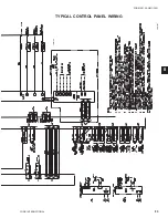
Page 82: ...YORK INTERNATIONAL 82 FORM 201 25 NM1 302 TYPICAL CONTROL PANEL WIRING LD07168 FIG 23 TYPICAL CONTROL PANEL WIRING Maintenance ...

Page 83: ...FORM 201 25 NM1 302 83 YORK INTERNATIONAL TYPICAL CONTROL PANEL WIRING LD07166 8 LD07167 ...

Page 84: ... PRESSURE DROP CURVES ENGLISH FIG 25 CONDENSER WATER PRESSURE DROP CURVES ENGLISH Pressure Drop H 2 O Flow GPM U S LD07163 Flow GPM Pressure Drop H 2 O O P Q LD07162 PRESSURE DROP CHARTS YCRS MODEL NUMBER COOLER 0100SC 0120SC 0140SC O 0180SC 0200SC P 0220SC 0240SC Q YCRS MODEL NUMBER COOLER 0100SC 0120SC 0140SC S 0180SC 0200SC 0220SC 0240SC U ...

Page 85: ... CURVES SI FIG 27 CONDENSER WATER PRESSURE DROP CURVES SI Pressure Drop kPa Flow l s S U Pressure Drop kPa Flow l s Q P O LD07164 LD07165 PRESSURE DROP CHARTS 9 YCRS MODEL NUMBER COOLER 0100SC 0120SC 0140SC O 0180SC 0200SC P 0220SC 0240SC Q YCRS MODEL NUMBER COOLER 0100SC 0120SC 0140SC S 0180SC 0200SC 0220SC 0240SC U ...

Page 86: ...ressure drops are higher than with water Spe cial care must be taken not to exceed the maximum allowed Ethylene Glycol Propylene Glycol LCHLT C Concentration Concentration w w w w 6 5 5 4 12 13 2 18 20 0 23 25 2 28 30 4 32 34 6 35 38 TABLE 13 RECOMMENDED GLYCOL SOLUTION STRENGTHS ETHYLENE GLYCOL PROPYLENE GLYCOL B A C B A C FIG 28 GLYCOL SOLUTION STRENGTHS A Correction Factor B Temperature C Conce...

Page 87: ...3 495 x 2743 495 x 2743 540 x 3963 540 x 3963 540 x 3963 540 x 3963 Water Nozzle Connection Size inches 8 8 8 8 8 8 8 TABLE 15 PHYSICAL DATA SI MODEL YCRS 0100SC 0120SC 0140SC 0180SC 0200SC 0220SC 0240SC General Unit Data Nominal Unit Capacity Tons 81 101 120 145 164 179 194 Number of Independent Refrigerant Circuits 2 2 2 2 2 2 2 Nitrogen N2 Shipping Charge Ckt 1 Ckt 2 lbs Oil Charge Ckt 1 Ckt 2 ...

Page 88: ...8 200 289 400 350 500 231 591 230 252 250 350 450 201 481 YCRS0140SC 380 153 150 200 250 122 285 460 127 150 175 225 101 228 575 102 100 125 175 81 182 200 292 400 350 500 233 591 230 254 250 350 450 203 481 YCRS0180SC 380 154 150 200 250 123 285 460 127 150 175 225 101 228 575 102 100 125 175 81 182 200 370 400 450 600 296 708 230 323 400 400 500 258 642 YCRS0200SC 380 195 200 250 350 156 343 460...

Page 89: ...450 600 296 708 230 323 400 400 500 258 642 YCRS0180SC 380 195 200 250 350 156 343 460 162 150 200 250 129 280 575 129 150 175 225 103 224 200 370 400 450 600 296 708 230 323 400 400 500 258 642 YCRS0200SC 380 195 200 250 350 156 343 460 162 150 200 250 129 280 575 129 150 175 225 103 224 200 447 600 600 800 357 708 230 388 400 500 600 310 642 YCRS0220SC 380 235 250 300 400 188 343 460 194 200 250...

Page 90: ... 14 1 0 AWG 8 2 AWG 4 300 KCM 8 2 AWG YCRS0240SC 2 4 0 AWG 8 2 AWG 4 300 KCM 8 2 AWG 4 300 KCM 8 2 AWG CHILLER MODEL VOLT C O D E TERM BLK TERMINAL BLK CUSTOMER GROUND N F DIS SW N F DISC SW CUSTOMER GROUND CKT BRKR CKT BRKR CUSTOMER GROUND NOTES for Electrical Data on pages 88 93 1 Minimum Circuit Ampacity MCA is based on 125 of the rated load amps for the largest motor plus 100 of the rated load...

Page 91: ... KCM 6 1 0 AWG 6 350 KCM 6 1 0 AWG YCRS0120SC 2 0 500 KCM 4 3 0 AWG 6 350 KCM 6 1 0 AWG 250 500 KCM 4 3 0 AWG YCRS0140SC 2 0 500 KCM 4 3 0 AWG 6 350 KCM 6 1 0 AWG 250 500 KCM 4 3 0 AWG YCRS0180SC 17 2 0 500 KCM 4 3 0 AWG 250 500 KCM 4 3 0 AWG 250 500 KCM 4 3 0 AWG YCRS0200SC 2 0 500 KCM 4 3 0 AWG 250 500 KCM 4 3 0 AWG 250 500 KCM 4 3 0 AWG YCRS0220SC 2 2 4 0 AWG 2 6 1 0 AWG 2 3 0 250 KCM 4 3 0 AWG...

Page 92: ...275 400 350 350 122 285 122 285 460 227 250 300 300 101 228 101 228 575 182 200 225 250 81 182 81 182 200 603 800 700 800 233 591 296 708 230 526 600 600 700 203 481 258 642 YCRS0180SC 380 318 400 400 450 123 285 156 343 460 262 400 300 350 101 228 129 280 575 210 250 250 300 81 182 103 224 200 666 800 800 800 296 708 296 708 230 581 600 700 800 258 642 258 642 YCRS0200SC 380 351 400 400 500 156 3...

Page 93: ... 2 2 0 500 KCM 2 4 3 0 AWG 2 250 500 KCM 2 4 3 0 AWG YCRS0100SC 2 4 0 AWG 8 2 AWG 4 300 KCM 6 1 0 AWG YCRS0120SC 2 300 KCM 6 1 0 AWG 4 300 KCM 6 1 0 AWG YCRS0140SC 2 300 KCM 6 1 0 AWG 6 350 KCM 6 1 0 AWG YCRS0180SC 40 2 0 500 KCM 4 3 0 AWG 250 500 KCM 4 3 0 AWG YCRS0200SC 2 0 500 KCM 4 3 0 AWG 250 500 KCM 4 3 0 AWG YCRS0220SC 2 0 500 KCM 4 3 0 AWG 250 500 KCM 4 3 0 AWG YCRS0240SC 2 0 500 KCM 4 3 0...

Page 94: ...VALVE 300 PSI EACH SYSTEM C G Z X ORIGIN B D C F C L G H I E A XL1 XL2 ZD1 XD1 XD2 SYS 2 1 1 8 O D LIQ CONN SYS 1 1 1 8 O D LIQ CONN SYS 1 1 5 8 O D DISCH CONN SYS 2 1 5 8 O D DISCH CONN ZD1 G C Y X ORIGIN 10 1 4 BB CC 6 3 8 3 3 8 AA 5 1 8 4 HOLES Ø3 4 FOR MOUNTING BOLTS VIEW SHOWING MOUNTING LOCATIONS M X TO RIGGING HOLE HOLES RIGGING Ø1 1 2 L P Q O N K J R TO COOLER CONN C L SYS 1 2 LIQ CONNS YD...

Page 95: ...XD1 16 15 16 16 15 16 16 15 16 16 15 16 16 15 16 16 15 16 16 15 16 XD2 16 5 16 16 5 16 16 5 16 16 5 16 16 5 16 16 5 16 16 5 16 YD1 13 7 8 13 7 8 10 9 16 17 1 2 17 1 2 17 1 2 17 1 2 YD2 13 7 8 10 9 16 10 9 16 17 1 2 17 1 2 17 1 2 17 1 2 ZD1 49 1 4 49 1 4 54 7 8 51 13 16 51 13 16 51 13 16 51 13 16 ZD2 49 1 4 54 7 8 54 7 8 51 13 16 51 13 16 51 13 16 51 13 16 DIMENSIONS ENGLISH CONT D 9 NOTES 1 CLEARA...

Page 96: ...m MODEL AA BB CC YCRS0100SC 2937 864 603 YCRS0120SC 2937 864 603 YCRS0140SC 2937 864 603 YCRS0180SC 4137 914 654 YCRS0200SC 4137 914 654 YCRS0220SC 4137 914 654 YCRS0240SC 4137 914 654 G C Y X ORIGIN 260 BB CC 162 86 AA 130 4 HOLES Ø19 FOR MOUNTING BOLTS VIEW SHOWING MOUNTING LOCATIONS M X TO RIGGING HOLE HOLES RIGGING Ø1 1 2 L P Q O N K J R TO COOLER CONN C L SYS 1 2 LIQ CONNS YD1 YD2 ZL1 SYS 1 2...

Page 97: ... 3533 4515 4515 4515 4515 B 1522 1568 1568 2118 2118 2118 2118 C 760 797 797 1346 1346 1346 1346 D 1524 1524 1524 1524 1524 1524 1524 E 848 848 848 998 998 998 998 F 1432 1432 1432 2040 2040 2040 2040 G 1432 1432 1432 2040 2040 2040 2040 H 1169 1169 1169 1722 1722 1722 1722 I 1169 1169 1169 1722 1722 1722 1722 J 1988 1988 1988 2003 2003 2003 2003 K 975 1027 1027 1075 1075 1075 1075 L 601 601 601 6...

Page 98: ...NGLISH TABLE 30 NEOPRENE VMCTYPE RD 4SELECTIONS MODEL A B C D YCRS0100SC RED RED RED RED YCRS0120SC RED RED RED RED YCRS0140SC RED RED RED RED YCRS0180SC GREEN GREEN GREEN GREEN YCRS0200SC GREEN GREEN GREEN GREEN YCRS0220SC GREEN GREEN GREEN GREEN YCRS0240SC GREEN GREEN GREEN GREEN TABLE 29 1 ISOLATOR SELECTIONS VMC TYPE CP 2 X MODEL A B C D YCRS0100SC 28 28 28 28 YCRS0120SC 31 31 31 31 YCRS0140SC...

Page 99: ...R CP 2 28 1800 816 1 0 26 Green CP 2 31 2200 998 0 83 21 0 Gray CP 2 35 3000 1360 0 7 17 7 Gold TABLE 32 ISOLATOR BRACKET DIMENSIONS ITEM E F G ENG 1 3 8 3 4 5 16 SI 35 19 8 ITEM A B C D ENG 3 6 3 8 10 1 4 5 1 8 SI 76 162 260 130 TYPE A C E H HD W X Y R 4 or 3 6 250 0 4 1 625 2 75 4 625 5 0 55 RD 4 76mm 159mm 10mm 41mm 70mm 118mm127mm 14mm LD07769 LD07770 LD07771 LD07772 TABLE 31 1 ISOLATOR DETAIL...

Page 100: ...5 75 65 62 82 YCRS0200SC 76 73 73 5 80 79 5 76 66 62 83 YCRS0220SC 76 74 74 81 80 5 77 66 5 62 84 YCRS0240SC 76 74 75 82 81 5 78 67 62 85 OCTAVEBANDHZ A B C D E F G H I J K L M N X AWMR 2 381mm 152mm 76mm 19 19mm 191mm 95mm 13mm 241mm 17mm 368mm 184mm 432mm 19mm 50 5XX 10NC 16mm TABLE 35 AWMR DIMENSIONS A B C D E F G H I J K L M N X AWMR 2 15 6 3 3 4 1 7 1 2 3 3 4 1 2 9 1 2 5 8 14 5 7 1 4 17 3 4 5...

Page 101: ...P CONTROL PANEL BDT DISCHARGE TEMPERATURE ECH CRANK CASE HEATER BECT CHILLED ENTERING TEMPERATURE FHP HIGH PRESSURE CUTOUT BLCT CHILLED LEAVING TEMPERATURE XCMTB COMPRESSOR MOTOR TERMINAL BOX BOP OIL PRESSURE YSV SOLENOID VALVE BOT OIL TEMPERATURE YLLSV LIQUID LINE SOLENOID VALVE BSP SUCTION PRESSURE ZCPR COMPRESSOR BST SUCTION TEMPERATURE LD06624 COMPRESSORS 9 ...

Page 102: ...YORK INTERNATIONAL 102 FORM 201 25 NM1 302 SECTION 10 SPARE PARTS Thisinformationwillbeavailableatalaterdate Spare Parts ...

Page 103: ...ter systems and drain the heat exchanger section of the systems If no isolation valves are installed it may be necessary to drain the complete system If glycol or similar solutions have been used in the water system or chemical additives are contained the solution MUST be disposed of in a suitable and safe manner Under NO circumstances should any system con taining glycol or similar solutions be d...

Page 104: ...1 1001 www york com P O Box1592 York PennsylvaniaUSA 17405 1592 Subject to change without notice Printed in USA Copyright by York International Corporation 2002 ALL RIGHTS RESERVED Form 201 25 NM1 302 New Release ...

Reviews: