YORK INTERNATIONAL
22
FORM 201.25-NM1 (302)
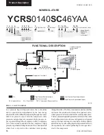
Option Flanges
One of two types of flanges may be fitted depending
on the customer or local Pressure Vessel Code require-
ments. These are Victaulic-Adapter flanges or weld
flanges. Victaulic-Adapter flanges are supplied loose
for field installation and weld flanges are factory fit-
ted. Flange dimensions are to ISO 7005 - NP10
(BS 4504 - NP10).
REFRIGERANT RELIEF VALVE PIPING
The cooler and condenser are each protected against
internal refrigerant overpressure by refrigerant relief
valves. Refer to Section 9 for details.
It is recommended that each valve should be piped to
the exterior of the building so that when the valve is
activated the release of high pressure gas and liquid
cannot be a danger or cause injury.
The size of any pipework attached to a relief valve must
be of sufficient diameter so as not to cause resistance
to the operation of the valve. For piping size require-
ments and specifications, refer to ASHRE-15 (latest
edition).
If relief pipework is common to more than one valve
its cross sectional area must be at least the total re-
quired by each valve. Valve types should not be mixed
on a common pipe. Precautions should be taken to en-
sure that the exit of relief valves/vent pipe remain clear
of obstructions at all times.
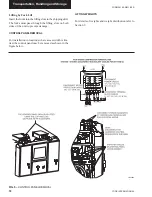
CONDENSER COOLING LIQUID SYSTEMS
YORK YCB/Remote Air-cooled Condenser or Evapo-
rative Condenser may be used – Refer to Installation &
Operation Instructions per manufacturer.
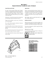
FIG. 10 –
VICTAULIC - ADAPTER FLANGES
CONDENSER PIPING
Discharge Lines
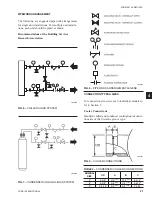
Pressure loss in the discharge line increases the power
to capacity ratio (kW/ton) of the system and decreases
the compressor capacity. This is illustrated in Figure
11. ASHRAE recommends a saturation temperature
change of 1°F based on frictional pressure drop for dis-
charge line sizing. Table 3 contains discharge line sizing
data for refrigerant R22. Capacities are for a condens-
ing temperature of 105°F and correction factors are
given at the bottom of the tables for other condensing
temperatures.
Liquid Lines
Pressure drop in liquid lines causes flashing of the refrig-
erant and reduction in pressure at the liquid feed device.
ASHRAE recommends that systems be designed so that
the pressure drop be no more than 1 to 2°F change in
saturation temperature. Table 3 contains liquid line sizing
data for refrigerants R-22 based on frictional pressure
drop causing a 1°F change in saturation temperature.
Liquid sub-cooling is the only means of overcoming the
liquid line pressure loss to ensure liquid entering the ex-
pansion device. Insufficient sub cooling may lead to flash-
ing of liquid refrigerant in the liquid line, which may result
in degradation of system performance. Liquid line risers
are an additional source of pressure loss. The loss in the
risers is approximately 0.5 psi per foot of liquid lift
(ASHRAE). Other losses include those caused by ac-
cessories like solenoid valves, filter driers, hand valves,
etc. Liquid lines from the condensers to the receivers
should be sized for a refrigerant velocity of 100 fpm or
less to ensure positive gravity flow without backup of
liquid flow.
Installation
LD06602
FIG. 11 –
EFFECT OF SUCTION AND DISCHARGE
LINE PRESSURE DROP ON CAPACITY
AND POWER. (R-22 system operating at
100°F saturated condensing and 40°F
saturated evaporating temperature. Energy
percentage is rated at kW/ton.)
LD07360

