YORK INTERNATIONAL
72
FORM 201.25-NM1 (302)
Micropanel
The anti-recycle timer controls the minimum time be-
tween starts for each compressor. This is the time avail-
able for the heat build up caused by inrush current at
start to be dissipated before the next start. Insufficient
cooling time between starts can cause heat build up
and motor damage. A fast compressor start response is
needed in some applications and not in others.
Although the minimum setting allowed on this timer
will avoid excessive heat build up, adjusting the timer
for the longest period acceptable in each application
will reduce cycling and maximize motor life. 600 sec-
onds is recommended.
The microprocessor will accept a range of program-
mable values between 300 and 600 seconds.
Local/Remote Communications:
The panel can be programmed for ‘LOCAL’ or ‘RE-
MOTE’ communications. ‘LOCAL’ mode allows moni-
toring through the RS485 port only. ‘REMOTE’, al-
lows an external device such as an ISN or Remote Con-
trol Center to change setpoints and programming points.
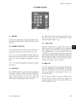
The ‘ ’ or ‘ ’ keys are used to change from ‘LO-
CAL’ to ‘REMOTE’.
Imperial/SI Units Display:
This allows the operator to select the display messages
to display ‘IMPERIAL’ (PSIG, °F, etc.) or
‘SI’ (Scien-
tific International, Barg, °C, etc.). The ‘ ’ or ‘ ’ keys
are used to change from ‘IMPERIAL’ to ‘SI’ units.
Automatic/Manual Lead/Lag:
The chiller may be selected for ‘MANUAL’ lead/lag
or ‘AUTOMATIC’ lead/lag. In some cases the opera-
tor may want to manually select the system that is de-
sired to be the lead system. In most cases, automatic
lead/lag is selected to allow the microprocessor to at-
tempt to balance run time between the systems. The
‘ ’ or ‘ ’ keys are used to change from ‘AUTO-
MATIC’ to ‘MANUAL’ lead/lag.
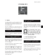
If ‘MANUAL’ control is desired, press the ‘
’
or ‘ ’
key. One of the following messages will be displayed:
System 1 or 2 can be selected as the lead by pressing
the ‘ ’ or ‘ ’ key. The ‘ENTER’ key must be pressed
to save the selection in memory.
Automatic/Manual Power Failure Restart:
The chiller may be selected for ‘AUTOMATIC’ or
‘MANUAL’ restart after a power failure. When
‘MANUAL’ is selected, the chiller will not operate af-
ter power is reapplied until the chiller ‘ON/OFF’ switch
on the keypad is cycled ‘OFF’ and then ‘ON’.
Programming manual restart ensures that re-setting
the emergency stop device will not initiate a re-start
as required by EN 418 and EN60204-1.
9.3 INPUT/OUTPUT DISPLAY ROUTINE
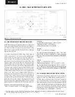
All digital and analog inputs and all digital outputs con-
nected to the microprocessor board (-AMB) and input/
output boards (-AIOB) can be viewed by pressing the
‘FUNCTION’ key and then pressing the ‘OPER DATA’
key. The ‘UP’ and ‘DOWN’ arrow keys can be used
to scroll through this information. This shows all -AMB
and -AIOB digital and analog inputs and all digital out-
puts including spares.
The currents to the slide valves – YSV
are not shown.
Each analog input display will include:
• Name of the measured value
(example: Sys 1 Suct Pr)
• Input plug to -AMB or AIOB (example: J13-7)
• Voltage read on input
• Converted value (example: 54.3 PSIG [3.75 BARG])
L O C A L
/
R E M O T E
M O D E
L O C A L
D I S P L A Y
U N I T S
I M P E R I A L
L E A D
/
L A G
C O N T R O L
A U T O M A T I C
L E A D / L A G
C O N T R O L
M A N U A L
S Y S
2
L E A D
L E A D / L A G
C O N T R O L
M A N U A L
S Y S
1
L E A D
P O W E R
F A I L
R E S T A R T
A U T O M A T I C


