YORK INTERNATIONAL
10
FORM 201.25-NM1 (302)
gas is compressed in volume and increased in pressure
before exiting at a designed volume at the discharge end
of the rotor casing. Since the intake and discharge cycles
overlap, a resulting smooth flow of gas is maintained.
The rotors are housed in a cast iron compressor hous-
ing precision machined to provide optimal clearances
for the rotors. Contact between the male and female
rotor is primarily rolling on a contact band on each of
the rotor’s pitch circle. This results in virtually no ro-
tor wear and increased reliability.
The compressor incorporates a complete anti-friction
bearing design for reduced power input and increased
reliability. Four separated, cylindrical, roller bearings
handle radial loads. Angular-contact ball bearings
handle axial loads. Together they maintain accurate
rotor positioning at all pressure ratios, thereby mini-
mizing leakage and maintaining efficiency. A springless
check valve is installed in the compressor discharge
housing to prevent compressor rotor backspin due to
system refrigerant pressure gradients during shutdown.
Motor cooling is provided by suction gas from the
evaporator flowing across the motor. Redundant over-
load protection is provided using both thermistor and
current overload protection.
The compressor is lubricated by removing oil from the
refrigerant using an external oil separator.
A 350 watt (115V 1 Ø 60 Hz) immersion heater is lo-
cated in the compressor. The heater is temperature ac-
tivated to prevent refrigerant condensation.
Motor Starting
Compressor motor starting is Star/Delta (S/D) open
transition. The starter utilizes 3 motor contactors, a tran-
sition delay relay and a start relay. The starter allows
inrush current to be limited to approximately 33% LRA
for the first 4 to 10 seconds, with current increasing to
normal running current when the Delta connection is
completed.
When the microprocessor initiates a start signal to run
a compressor, the applicable relays are energized. The
transition of the relay contacts enable the ‘Star’ con-
nection of the motor start. The ‘Star’ connection of the
motor start is enabled for 4 to 10 seconds depending
upon motor current as sensed by the microprocessor.
Normally, the transition to Delta takes 10 seconds if
current is below 125% FLA. If motor current exceeds
125% FLA, the transition is made to Delta as long as
the “Star” has been enabled for at least 4 seconds.
Capacity Control
The compressors will start at the minimum load posi-
tion and provide a capacity control range from 10% to
100% per compressor using a continuous function slide
valve. The microprocessor controlled output pressure
regulating capacity control valve will command com-
pressor capacity independent of control valve input pres-
sure and balance the compressor capacity with the cool-
ing load.
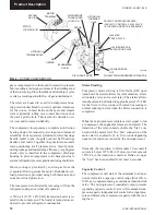
FIG. 2 –
SCREW COMPRESSOR
Product Description
LD03668
SUCTION
GAS IN
MOTOR
TERMINALS
LIFTING LUG
THREADED HOLE
OIL
HEATER
ECONOMIZER
GAS IN
DISCHARGE CASE
OIL INLET FROM CONDENSER CODING COIL
DISCHARGE GAS
OUT
OIL FILTER BLEED &
EVACUATION POINT
OIL FILTER
COVER PLATE
CAPACITY CONTROL SOLENOID
(CAPACITY CONTROL, 3-WAY VALVE,
IS LOCATED UNDER THE SOLENOID)
LIFTING LUG
THREADED
HOLE
OIL PRESSURE
TRANSDUCER
LOCATION
ROTOR
STATOR
LOCKING BOLT


