YORK INTERNATIONAL
20
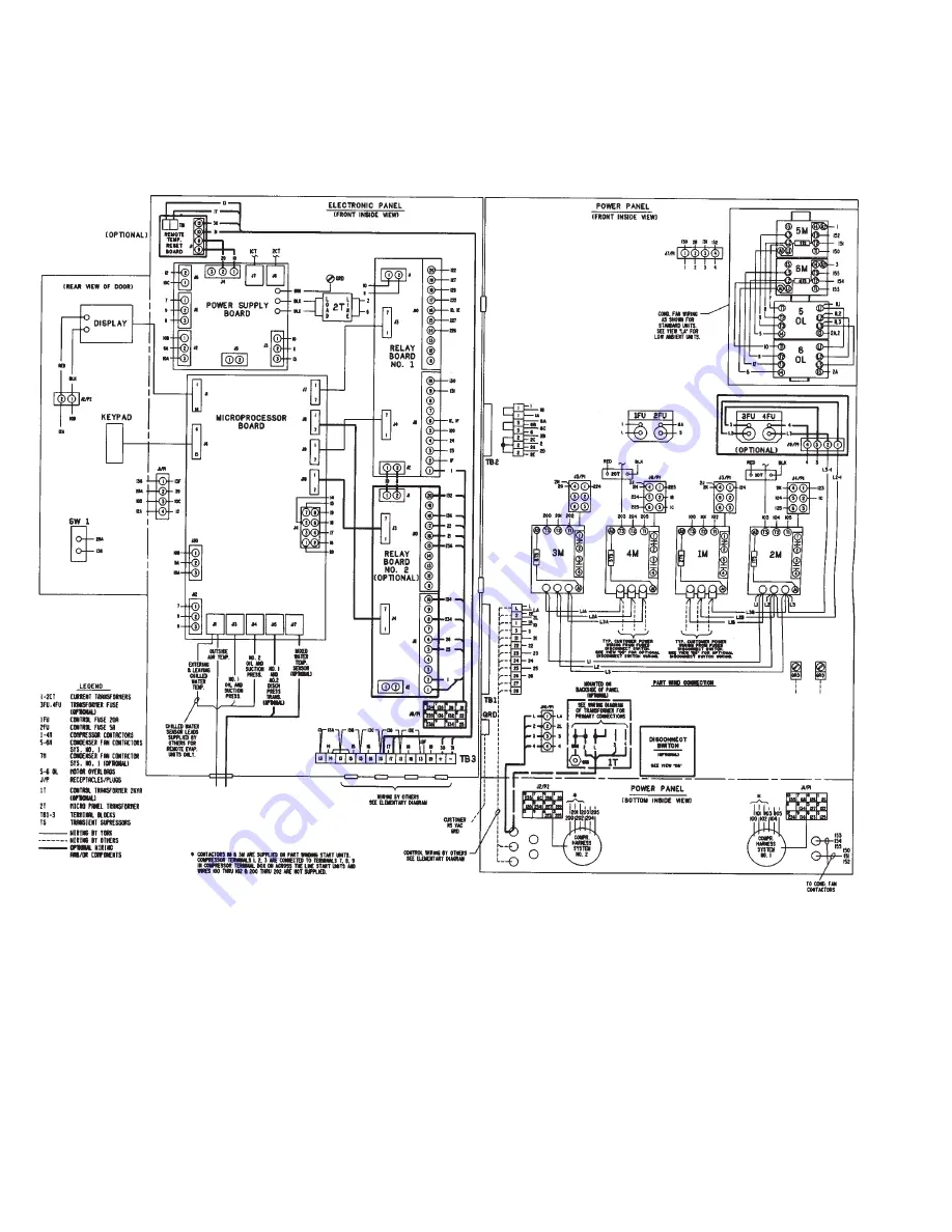
CONNECTION DIAGRAM
BOX, ELEC.
YCA 50 - 90 (ARI) STANDARD AND REMOTE EVAPORATOR UNITS
LD01996
FIG. 7
Page 1: ...AIR COOLED RECIPROCATING HERMETIC Supersedes 150 44 NM3 in ERR only Form 150 44 NM4 395 60 HZ MODELS YCAZ33BA3 YCAZ44BA3 YCAZ74BB3 YCAZ77CB3 YCAZ88DB3 STYLE A With EPROM 031 01096C001 Standard Brine M...
Page 2: ...eside the building WARNING HIGH VOLTAGE is used in the operation of this equipment DEATH OR SERIOUS INJURY may result if personal fail to observe safety precautions Work on electronic equipment should...
Page 3: ...L DATA Cooler Code B C D Condenser Code A B S Special X Blank if not used Design Level Type Start P Part Wind A Across The Line Voltage Code 17 200 3 60 28 230 2 60 40 380 3 60 46 460 3 60 50 380 415...
Page 4: ...NTERNATIONAL 4 CONDENSER FANS CONTROL PANEL POWER PANEL SYS 1 COMPRESSOR COOLER INLET SHIPPING BRACKET Removed After Installation HEATER COOLER OUTLET COOLER SYS 2 COMPRESSOR 26195A R FIG 1 UNIT COMPO...
Page 5: ...FORM 150 44 NM4 5 YORK INTERNATIONAL FIG 1 UNIT COMPONENTS Cont d LD01980 HOT GAS BY PASS OPTIONAL SYSTEM 1 25996A...
Page 6: ...294A 6 CYLINDER MODEL Z COMPRESSOR OIL PRESSURE ACCESS CONN OIL LEVEL SIGHT GLASS OIL CHARGING VALVE TERMINAL BOX CAPACITY CONTROL SOLENOID DISCHARGE STOP VALVE DATA PLATE OIL PUMP CRANKCASE HEATER 27...
Page 7: ...F by resetting standard controls 2 Operation below 25 F requires the Optional Low Ambient Kit Minimum recommended operating temperature is 0 F 3 Operation above 115 F requires Optional High Ambient Ki...
Page 8: ...Steps CONDENSER DWP 450 PSIG 2 2 2 2 2 NO OF FANS 42 Dia Direct Drive HP KW Each 850 RPM 3 2 5 3 2 5 3 2 5 3 2 5 3 2 5 CFM TOTAL 30 300 30 300 34 400 34 400 34 400 COOLER DUAL CIRCUITED DWP 235 PSIG R...
Page 9: ...e clearances shown above and area under the unit must be kept clear of all obstructions that would impede free air flow to the unit In installations where winter operation is in tended and snow accumu...
Page 10: ...lectrical Code and using copper connectors only Field wiring must also comply with local codes 7 A ground lug is provided for each compressor system to accommodate field grounding conductor per N E C...
Page 11: ...880 675 11 0 172 765 587 9 6 86 383 294 4 8 68 8 306 235 3 8 LD01985 CONTROL POWER SUPPLY UNIT CONTROL MIN CIRCUIT MAX DUAL NON FUSED VOLTAGE POWER SUPPLY AMPACITY ELEMENT FUSE SIZE DISC SW SIZE Std...
Page 12: ...arge Lethal voltages exist within the control panel Be fore servicing open and tag all disconnect switches Refer to WARNINGS on page 2 3 Open unit only to install water piping system Do not remove pro...
Page 13: ...lations precautions should be taken to protect the unit from tampering by or injury to unautho rized persons Screws and or latches on access panels will prevent casual tempering However further safety...
Page 14: ...P 2 26 CP 2 26 CP 2 31 CP 2 31 Z88DB3 Mason Ind CIP C 1000 CIP C 1000 CIP C 2100 CIP C 2100 VMC CP 2 26 CP 2 26 CP 2 31 CP 2 31 CU CU Z33BA3 Mason Ind CIP C 1000 CIP C 1000 CIP C 1695 CIP C 1695 VMC C...
Page 15: ...chilled liquid lines that are exposed to outdoor ambients should be wrapped with a supplemental heater cable and insulated to protect against freeze up during low ambient periods and to prevent forma...
Page 16: ...t shown install a cycling device in series with the flow switch FLSW See Note 3 for contact rating and wiring specifications 5 To stop unit Emergency Stop with contacts other than those shown install...
Page 17: ...y contacts must be suppressed with YORK P N 031 00808 suppres sor across the relay contactor coil which acti vates the contacts Any contacts connected to flow switch inputs or BAS inputs on terminals...
Page 18: ...YORK INTERNATIONAL 18 LD01992 LD01993 LD01994 FIG 6 SYSTEM WIRING CONNECTION DIAGRAM SYSTEM WIRING YCA 50 90...
Page 19: ...FORM 150 44 NM4 19 YORK INTERNATIONAL FIG 6 SYSTEM WIRING Cont d...
Page 20: ...YORK INTERNATIONAL 20 CONNECTION DIAGRAM BOX ELEC YCA 50 90 ARI STANDARD AND REMOTE EVAPORATOR UNITS LD01996 FIG 7 CONNECTION DIAGRAM...
Page 21: ...FORM 150 44 NM4 21 YORK INTERNATIONAL FIG 7 CONNECTION DIAGRAM Cont d LD01997 LD01998 LD01999...
Page 22: ...d water tempera ture reset can be accomplished by user supplied dry contacts Compressor starting stopping and loading unloading decisions are performed by the Microprocessor to main tain leaving water...
Page 23: ...relay coils will be at 12VDC potential CURRENT TRANSFORMER C T A C T on the 3f power wiring of each motor sends AC signals proportional to motor current to the Power Sup ply Board which rectifies and...
Page 24: ...TERIOR POWER SUPPLY BOARD 2T TRANSFORMER RELAY OUTPUT BOARD 1 LOCATION OF OPTIONAL RELAY OUTPUT BOARD 2 TB3 CONNECTIONS FOR FLOW SWITCH LEAD LAG SELECTOR EMS BAS CONTROLS LCD DISPLAY BOARD MICROPROCES...
Page 25: ...less than the limit values which are being displayed If a message is required to be updated faster than ev ery 2 seconds the appropriate key for the desired dis play may be pushed and held Updating wi...
Page 26: ...selected by the S1 Dip Switch on the Microprocessor Board Fig 12 Proper programming of the switch is important during commissioning of the chiller The OP TIONS display allows a means of verifying the...
Page 27: ...H U N I T S R E A D O U T M E T R I C U N I T S R E A D O U T R E T U R N W A T E R C O N T R O L L E A V I N G W A T E R C O N T R O L L O C A L C O N T R O L M O D E R E M O T E C O N T R O L M O D...
Page 28: ...ITCH 5 OPEN Display messages will show units of measure in En glish units F PSI etc CLOSED Display messages will show units of measure in Metric units C kPa etc SWITCH 6 OPEN This MUST be selected for...
Page 29: ...In this mode maximum chiller efficiency will be achieved If the Low Ambient option is installed the fan control will automatically change to pressure con trol at temperatures below 25 F See page 66 f...
Page 30: ...and as individual systems The messages displayed will include running status cooling demand fault sta tus external cycling device status and anti recycle timer status The display will be a single mes...
Page 31: ...t will shut down causing total loss of cool ing When this message appears discharge pressure has exceeded the user programmable threshold and the micro is unloading the affected system to prevent shut...
Page 32: ...G H D S C H C H I L L E R F A U L T H I G H A M B I E N T T E M P S Y S 1 L O W O I L P R E S S C H I L L E R F A U L T 1 1 5 V A C U N D E R V O L T A G E S Y S 1 L O W S U C T I O N S Y S 2 L O W S...
Page 33: ...l able data after any one of the following keys is pressed PROGRAM SET SCHEDULE HOLIDAY OPER DATA HISTORY Cancel Key The CANCEL key allows the user to change errors in the data being programmed into m...
Page 34: ...OUT The DISCHARGE CUT OUT is a microprocessor back up for the mechanical high pressure cut out located in each refrigerant circuit Typically chillers with air cooled condensers should have the cut ou...
Page 35: ...tablish the high ambient cut out point If the ambi ent rises above this point the chiller will shut down Re start can occur when temperature drops below the cut out This only applies to outdoor air co...
Page 36: ...t suit his needs Motor heating is a result of inrush current when the motor is started This heat must be dissipated before another start takes place or motor damage may result The anti recycle timer a...
Page 37: ...because water temperature is dropping quickly This provides demand limiting and reduces loader compressor cycling and overshoot If quick response is needed RATE SENSI TIVITY can be programmed accordi...
Page 38: ...s played when the SET TIME key is pressed To program the day time and date first press the AD VANCE DAY key until the appropriate day of the week is displayed The day will advance each time the key is...
Page 39: ...e days to view times programmed use the ADVANCE DAY KEY not the ENTER KEY This will assure that after viewing MONDAY that the ENTER KEY is not pressed changing times programmed for the rest of the wee...
Page 40: ...pressor and loader cycling enabling LEAVING WATER CONTROL to be used in most applications The con trol algorithm utilizes PID control For batch and process applications LEAVING WATER CONTROL will all...
Page 41: ...ecause the anti recycle timer is still timing out The effects can be re duced by programming the anti recycle timer Page 36 for a minimum of 300 seconds if it isn t already programmed for 300 seconds...
Page 42: ...gh return water temperature con trol is being utilized the object is to provide constant design leaving water temperature It is the Design Leaving Water Temperature setpoint LWT which must be programm...
Page 43: ...ill attempt to load the chiller as fast as it can 30 seconds per stage unless the chiller has not run for 3 minutes This allows the chiller to gain control of the water temperature as quickly as possi...
Page 44: ...ding the loading unloading timers when water temperatures are in the RATE CONTROL RANGE or the CONTROL RANGE This allows the micro to react to abrupt downward changes in leaving or return water temper...
Page 45: ...recycle timer for a minimum of 300 seconds if it isn t already programmed for 300 seconds NOTE Whenever reprogramming the LWT CR keep in mind that the desired leaving water temp or target should be mi...
Page 46: ...ding the loading unloading timers when water temperatures are in the RATE CONTROL Additionally the actual rate of change RATE SENSI TIVITY of water temperature which the micro uses as a control refere...
Page 47: ...emperature drop across the evaporator fully loaded the microprocessor will be able to maintain the desired leaving water temperature by con trolling off of the return water temperature RWT Simply the...
Page 48: ...1 The Lead Comp 2 Steps Lag Comp Off Step is skipped on a temperature drop 2 The micro controls loading and unloading on a 10 STEP scale regardless of the num ber of stages present Therefore loading...
Page 49: ...steps of loading unloading although 10 steps is not available with the compressors utilized The chiller MUST be programmed for the number of steps which were ordered Otherwise improper operation and...
Page 50: ...rent is exceeding 120 FLA at the 3 second point the compressor will shut down After 4 seconds of operation motor current must be greater than 15 FLA but less than 115 FLA as long as the compressor con...
Page 51: ...motor stator These sensors are wired into the motor protector module located inside the Motor terminal box As the motor windings heat and cool the resistance of the motor temperature sensors will cha...
Page 52: ...below High Ambient Temperature Safety The High Ambient Temperature Safety assures that the chiller does not run in ambients above 130 F where potential malfunction of system mechanical and electri ca...
Page 53: ...he chance of tripping the relief valve due to a very high rate of rise in pressure resulting from a controls problem which would cause condenser water flow to be interrupted In this case the pressure...
Page 54: ...wn in Fig 19 History The HISTORY key allows the operator to remotely obtain a printout of information relating to the last 3 YORK INTERNATIONAL CORPORATION RECIPROCATING WATER CHILLERS SYSTEM STATUS 8...
Page 55: ...MPS 0 FLA SUCTION PRESSURE 61 PSIG DISCHARGE PRESSURE 80 PSIG OIL PRESSURE 1 PSID LIQUID LINE SOLENOID OFF RUN PERMISSIVE ON STAGES OF LOADING 1 FORWARD FANS 1 REVERSE FANS OFF HOT GAS BYPASS VALVE OF...
Page 56: ...essage informs the operator whether the Hot Gas Solenoid is ON or OFF The micro will activate the Hot Gas signal regardless of whether or not this option is installed The Run Time for SYS 1 since the...
Page 57: ...d 7 Lead Compr Loaded Lag Compr Unloaded 8 Lead Compr Loaded Lag Compr Unloaded 9 Lead Compr Loaded Lag Compr Loaded 10 Lead Compr Loaded Lag Compr Loaded On some STEPS actual Loading will NOT change...
Page 58: ...tively pressing the ENTER key will allow the operator to scroll through the information available in the SAFETY SHUTDOWN Buffer In the information that follows a sample message along with an explanati...
Page 59: ...P R E S S O R O N S Y S 1 C O M P R E S S O R O N The software designed to control fans whether or not they are present on the chiller as is the case on water cooled indoor units If an indoor unit exi...
Page 60: ...P S I G S Y S 2 O I L P R E S S U R E 7 4 P S I D The software designed to control tans whether or not they are present on the chiller as is the case on water cooled indoor units If an indoor unit ex...
Page 61: ...the S1 Dip Switches properly on the Microprocessor Board Details for doing this are discussed in the OPTIONS key section When AUTO Lead Lag is utilized the micro determines which compressor is assign...
Page 62: ...e Additionally the lag system will automatically become the lead any time the system switch on the Microprocessor Board of the compressor currently in the lead is placed in the OFF position This is al...
Page 63: ...for extended periods of months it may be desirable to disable the clock to save battery life The clock can then be reactivated and re programmed when the chiller is returned to service NOTE ALL PROGRA...
Page 64: ...positioning of this switch can then be verified by pushing the OPTIONS key and verifying that METRIC UNITS READOUT is programmed Page 26 EMS BAS CONTROLS The microprocessor is capable of REMOTE START...
Page 65: ...coil of the device must be suppressed with a user supplied YORK P N 031 00808 suppressor NOTE Remote Setpoint Reset will not operate when a Remote Control Center Option Kit is con nected to the Micro...
Page 66: ...ipped with 2 condenser fans The stan dard fan control strategy is fan cycling by outdoor am bient temperature with the low ambient cut out chiller shut down set at 25 F Above 25 F ambient 1 fan will t...
Page 67: ...ight glass If it is necessary to add oil connect a YORK oil pump to the oil charging valve but do not tighten the flare nut on the delivery tubing With the bottom suction end of the pump submerged in...
Page 68: ...ut into operation Place the System Switches to the ON position See the OPERATING SEQUENCE for unit operation The compressor will start and a flow of liquid should be noted in the liquid indicator Afte...
Page 69: ...it is running fully loaded Correct superheat setting is 10 12 F The superheat is the difference between the actual tem perature of the returned refrigerant gas entering the compressor and the temperat...
Page 70: ...mpressor will shut down 6 After 30 seconds of run time the oil pressure of the lead compressor must be a minimum of 20 PSID and the suction pressure must be a minimum of 50 of cut out 7 After 60 sec o...
Page 71: ...essary to charge oil refer to item 3 under the ANNUAL MAINTE NANCE section 3 Check the refrigerant circuit for leaks 4 Operating Pressures and Temperatures Check to see that operating pressures and te...
Page 72: ...ate for long periods of time J Be sure both discharge and suction stop valves are open before operating the unit 4 Suction and Discharge Valves The condition of the suction and discharge valves should...
Page 73: ...ctor relay coil con nected to these contacts must be suppressed with YORK P N 031 00808 supplied by others Otherwise nuisance faults may occur 0 F LOW AMBIENT OPTION The standard chiller is designed t...
Page 74: ...es sure of either system drops below 120 PSIG NOTE The corresponding compressor must be on for 4 sec before this fan is permitted to start 4 The fourth stage of fan control will energize fan 1 5M in t...
Page 75: ...ed from the compressor discharge to the cooler inlet The following text will explain how the hot gas solenoid is activated by the microprocessor in both return and in leaving water control LWT Control...
Page 76: ...zing the solenoid 1 4 Adjust the adjustment screw 2 in the clockwise direction to open the valve at a higher pressure sooner or in the counterclockwise direction to open the valve at a lower pressure...
Page 77: ...w be obtained from the micro panel Discharge Pressure unloading allows the microproces sor to unload a compressor when the discharge pres sure approaches a point nearing the discharge pres sure cut ou...
Page 78: ...both air and water cooled with or without options Items may be indicated on the printout which may not be present on the chiller Installation Limitations The following limitations must be adhered to F...
Page 79: ...pressed however it will be a snapshot of sys tem operating conditions at the instant that the fault occurred Additionally the Status indication that is noted in the printout will note the specific fau...
Page 80: ...IG 33 COMPLETED INSTALLATION FIG 34 WIRE GRILLE INSTALLATION 0001TG Parts List for Each Kit PART ITEM QTY DESCRIPTION 026 32301 000 4 1 Grille Top L H 026 32302 000 5 1 Grille Top R H 026 32303 000 6...
Page 81: ...es as needed 5 If the High Ambient Sunshield Kit or Disconnect Option is installed field adaption will be required where parts of the kits interfere Touch up exposed metal parts to prevent rust FIG 35...
Page 82: ...which the mi croprocessor can understand Whenever an offset is called for the change may be noted by the user by pressing the REMOTE RESET TEMP RANGE key on the keypad All refresh requirements normall...
Page 83: ...with an input of 4mA The temperature will be offset linearly according to the current 4 20mA ap plied The 4 20mA input signal should be connected to the and terminals on the TB3 Terminal Block at the...
Page 84: ...ective contactor contacts and contactor 2 Check contacts and contactor 3 Faulty high voltage wiring 3 Check wiring 4 High motor current stored in memory 4 Loose calibration resistors in J9 SYS 1 or J1...
Page 85: ...MBIENTTEMP 2 Temperature sensed incorrectly by thermistor 2 Verify actual ambient temperature immediately Cuts out on low ambient at probe with thermometer temperature 3 Check low ambient temperature...
Page 86: ...pressure programmed unload point or 1 Excessive load Check OPERATING LIMITATIONS Solenoid valve de energizes operating limitations have been exceeded Check programmed unloading point to load compresso...
Page 87: ...FORM 150 44 NM4 87 YORK INTERNATIONAL...
Page 88: ...4 121 249 8 50 0 122 251 6 50 6 123 253 4 51 1 124 255 2 51 7 125 257 0 52 2 126 258 8 52 8 127 260 6 53 3 128 262 4 53 9 129 264 2 54 4 130 266 0 55 0 131 267 8 55 6 132 269 6 56 1 133 271 4 56 7 134...