


33
JOHNSON CONTROLS
FORM 201.18-NM7
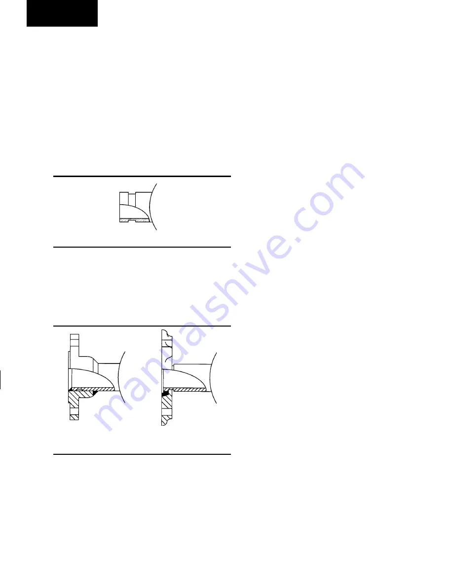
Option Flanges
One of two types of flanges may be fitted depending on
the customer or local Pressure Vessel Code requirements.
These are Victaulic-Adapter flanges, normally supplied
loose, or weld flanges which may be supplied loose or
ready fitted. Victaulic-Adapter and weld flange dimen
-
sions are to ISO 7005 - NP10.
REFRIGERANT RELIEF VALVE PIPING
Coolers and oil separators are each protected against
internal refrigerant overpressure by refrigerant relief
valves. For coolers, a pressure relief valve is mounted on
each of the main refrigerant lines connecting the cooler
to the compressors. On oil separators the pressure relief
valve is mounted on the side near top of the vessel body.
It is recommended that a piece of pipe is fitted to each
valve and directed so that when the valve is activated the
release of high pressure gas and liquid cannot be a danger
or cause injury. For indoor installations pressure relief
valves should be piped to the exterior of the building.
The size of any pipework attached to a relief valve must
be of sufficient diameter so as not to cause resistance to
the operation of the valve. Unless otherwise specified
by local regulations, table internal diameter depends on
the length of pipe required and is given by the following
formula:
D
5
= 1.447 x L
Where:
D = minimum pipe internal diameter
L = length of pipe in meters
If relief pipework is common to more than one valve its
cross sectional area must be at least the total required
by each valve. Valve types should not be mixed on a
common pipe. Precautions should be taken to ensure
that the outlet of relief valves/vent pipe remain clear of
obstructions at all times.
DUCTWORK CONNECTION
General Requirements
The following ductwork recommendations are intended
to ensure satisfactory operation of the unit. Failure to
follow these recommendations could cause damage to
the unit, or loss of performance, and may invalidate the
warranty.
When ducting is to be fitted to the fan discharge it is
recommended that the duct should be the same cross
sectional area as the fan outlet and straight for at least
three feet (1 meter) to obtain static regain from the fan.
Ductwork should be suspended with flexible hangers
to prevent noise and vibration being transmitted to the
structure. A flexible joint is also recommended between
the duct attached to the fan and the next section for the
same reason. Flexible connectors should not be allowed
to concertina.
The unit is not designed to take structural loading. No
significant amount of weight should be allowed to rest
on the fan outlet flange, deck assemblies or condenser
coil module. No more than 3 feet (1 meter) of light
construction ductwork should be supported by the unit.
Where cross winds may occur, any ductwork must be
supported to prevent side loading on the unit.
PIPEWORK ARRANGEMENT
The following is a suggested pipework arrangement for
single unit installations. For multiple unit installations,
each unit should be piped as shown.
CONNECTION TYPES & SIZES
For connection sizes relevant to individual models refer
to the Technical Data Section.
COOLER CONNECTIONS
Standard chilled liquid connections on all coolers are of
the Victaulic Groove type.
LD03521
FIG. 6 –
VICTAULIC GROOVE
Weld Flange
Victaulic Adapter
LD03523
FIG. 7 –
FLANGE ATTACHMENTS
Installation
Summary of Contents for YCAS 0138EB
Page 50: ...50 JOHNSON CONTROLS This page intentionally left blank...
Page 61: ...61 JOHNSON CONTROLS FORM 201 18 NM7 This page intentionally left blank 7...
Page 70: ...70 JOHNSON CONTROLS Technical Data FIG 22A CONTROL PANEL COMPONENT LOCATIONS...
Page 71: ...71 JOHNSON CONTROLS FORM 201 18 NM7 LD03280 FIG 22B POWER PANEL COMPONENT LOCATION 7...
Page 72: ...72 JOHNSON CONTROLS Technical Data LEGEND LD03281...
Page 73: ...73 JOHNSON CONTROLS FORM 201 18 NM7 LD03282 LD03283 LD03284 7...
Page 74: ...74 JOHNSON CONTROLS Technical Data CONNECTION DIAGRAM SYSTEM WIRING LD06256 LD03231 LD03232...
Page 75: ...75 JOHNSON CONTROLS FORM 201 18 NM7 COMPRESSOR TERMINAL BOX LD03233 7...
Page 76: ...76 JOHNSON CONTROLS LD03285 Technical Data...
Page 77: ...77 JOHNSON CONTROLS FORM 201 18 NM7 3 4 5 6 3 4 5 6 7 8 5 6 3 4 7 8 9 10 LD06840A 7...
Page 181: ...181 JOHNSON CONTROLS FORM 201 18 NM7 NOTES...
Page 182: ...182 JOHNSON CONTROLS This page intentionally left blank...
Page 183: ...183 JOHNSON CONTROLS FORM 201 18 NM7 This page intentionally left blank...


