background image

P5417090

Installation

and

Maintenance

Manual

INVERTER-DRIVEN

MULTI-SPLIT SYSTEM

HEAT PUMP

AIR CONDITIONERS

Type

Model

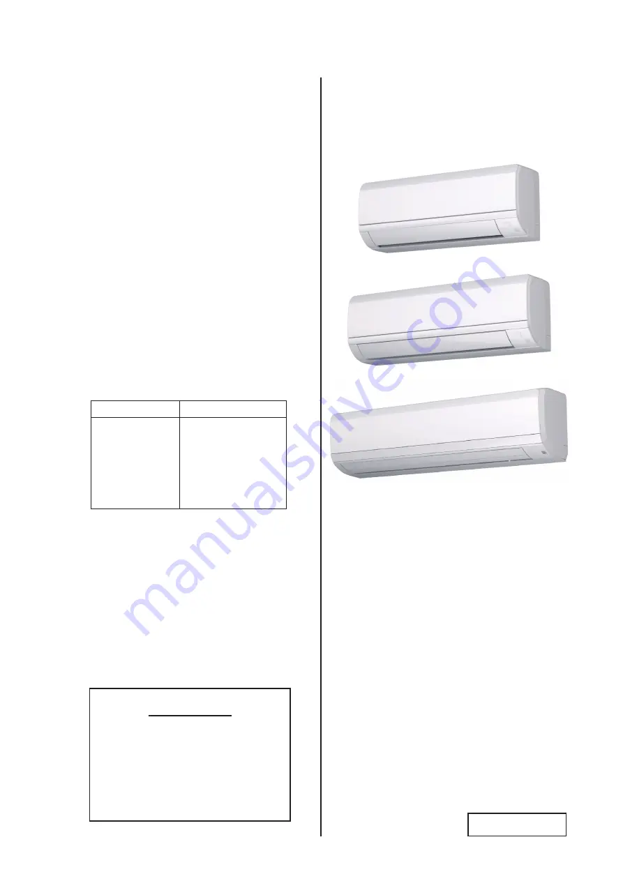
Wall Mount

TIWM006B22S

TIWM008B22S

TIWM012B22S

TIWM015B22S

TIWM018B22S

TIWM024B22S

TIWM030B22S

IMPORTANT:

READ AND UNDERSTAND

THIS MANUAL BEFORE

INSTALLING THIS HEAT 

PUMP AIR CONDITIONER. 

KEEP THIS MANUAL FOR 

FUTURE REFERENCE.

Summary of Contents for TIWM006B22S

Page 1: ...T SYSTEM HEAT PUMP AIR CONDITIONERS Type Model Wall Mount TIWM006B22S TIWM008B22S TIWM012B22S TIWM015B22S TIWM018B22S TIWM024B22S TIWM030B22S IMPORTANT READ AND UNDERSTAND THIS MANUAL BEFORE INSTALLIN...

Page 2: ......

Page 3: ...for a specific temperature range For optimum performance and long life operate this unit within the range limits according to the table below This manual should be considered as a permanent part of th...

Page 4: ...sition of Piping Connection 16 6 Refrigerant Piping Work 19 6 1 Piping Materials 19 6 2 Piping Connections 20 7 Condensate Piping 22 8 Electrical Wiring 24 8 1 General Check 25 8 2 Electrical Wiring C...

Page 5: ...as needed This system should be installed by personnel certified by Johnson Controls Inc Personnel must be qualified according to local state and national building and safety codes and regulations In...

Page 6: ...a hospital or other facility where electromagnetic waves are generated from nearby medical and or electronic devices be prepared for noise and electronic interference Electromagnetic Interference EMI...

Page 7: ...nit near any sanitary sewers where corrosive gases may be present If you do toxic gases can seep into breathable air spaces and can cause respiratory injuries If the condensate pipe is installed incor...

Page 8: ...source can become toxic or cause fire When installing the unit and connecting refrigerant piping keep all piping runs as short as possible and make sure to securely connect the refrigerant piping befo...

Page 9: ...at the terminal connection Turn OFF and disconnect the unit from the power supply when handling the service connector Do not open the service cover or access panel to the indoor or outdoor units witho...

Page 10: ...lines where flammable and toxic gases can coalesce Inspect the condensate pan before the onset of winter to drain away all accumulated moisture in the pan The heat exchanger of indoor unit overheats w...

Page 11: ...only for a single operation and individual operations for twin triple and quad combinations However it cannot be used for the following operations Operation with 2 Controllers CIR01 and wired control...

Page 12: ...ighter 3 Vacuum Pump 13 Charging Cylinder 4 Refrigerant Gas Hose 14 Manifold Gauge 5 Megohmmeter 15 Wire Cutter 6 Copper Pipe Bender 16 Gas Leak Detector 7 Manual Water Pump for Indoor Unit 17 Leveler...

Page 13: ...he wall is able to withstand the weight of the indoor unit If there is insufficient structural integrity noise in the form of vibration generated by the unit is magnified 5 Verify that the supporting...

Page 14: ...12 1 25 1 2 13 7 16 11 1 2 12 1 2 13 2 3 16 55 1 25 7 16 11 1 2 13 1 1 4 32 3 16 5 11 13 16 300 1 3 4 45 31 1 8 790 2 9 16 65 1 Left Rear Side Hole for Piping 2 9 16 65 Right Rear Side Hole for Pipin...

Page 15: ...9 16 344 7 15 16 201 7 3 16 182 1 3 4 44 9 16 15 3 16 5 9 1 16 230 9 7 16 239 11 13 16 300 9 16 14 2 5 8 66 1 5 8 42 7 8 22 1 1 8 28 7 8 22 1 3 4 45 1 1 4 32 1 1 4 32 1 5 8 42 1 1 8 28 7 8 22 1 1 8 28...

Page 16: ...2 5 16 58 9 1 16 230 15 1 8 384 11 16 18 3 8 9 5 7 8 150 15 3 4 400 14 15 16 380 5 16 8 15 16 24 15 16 24 3 1 16 78 1 1 8 28 Min 3 15 16 100 Min 3 15 16 100 9 1 16 230 15 1 8 384 1 1 2 38 15 16 24 1...

Page 17: ...e sloping down and away from the unit as shown in the figure at right Condensate piping connection can be performed on both right side and left side of the unit 5 Open the piping hole slightly lower t...

Page 18: ...the upper part of the indoor unit to the mounting plate NOTE Avoid contact with refrigerant or refrigerant oil to the upper part of indoor unit If the unit cover plate comes into contact with these s...

Page 19: ...is reattached insert the catches for air filter to complete b Release the two 2 catches and pull the air filter downward to remove it c Open the flat panel fully and push the right arm shaft inward Af...

Page 20: ...igerant Gas Pipe Connection j With Flare Nut 1 Direction of Piping Installation Determine the direction of the piping connection according to the layout of the installation site In the case that the p...

Page 21: ...the pipe remove the knock out panel and put the pipe into the straight position by holding part with your hand Make the pipe straight before bending in order to prevent the pipe from getting kinked i...

Page 22: ...supplied Make sure to seal the hole in the wall completely in order to prevent rainwater and outdoor air from entering When using putty for sealing avoid contact with the wall since it may result in o...

Page 23: ...erant piping lengths depend on the combination with the outdoor unit Refer to the Installation and Maintenance Manual for the outdoor unit 2 Select the piping size from the following table For details...

Page 24: ...erform the flaring work as shown below 6 2 Piping Connections 5 Wherever buried piping exists on site make sure there is a service doorway to provide adequate access to inspect piping sockets and elbo...

Page 25: ...uncouple the indoor unit from the mounting plate Do not apply excessive force to the flare nut when tightening If applied the flare nut may crack due to stress fracture and refrigerant leakage may oc...

Page 26: ...aces and damage to furniture and carpeting Avoid sloping the condensate piping upward as it will impede drainage Moisture will settle back into the unit and may cause water leakage when unit operation...

Page 27: ...ide condensate connection is performed remove the cap from the left side condensate and then attach this cap to the right side condensate in order to change the condensate connection from the right si...

Page 28: ...ischarge The ground resistance must be less than 1 megohm The grounding must be performed by authorized installers Disconnect or turn OFF the main power supply to prevent electrical shock when opening...

Page 29: ...it is less than one megaohm do not operate the system until the source of the electrical current drain is found and repaired B Check to ensure that the stop valves of the outdoor unit are fully opene...

Page 30: ...s 3 Total operating current is less than 12A Check for the recommended size GFCI shown in the table 8 1 Between indoor and outdoor units use dual conductor AWG18 0 82mm2 stranded copper cable for comm...

Page 31: ...cable can be used 1 Connect the power supply wirings L1 and L2 to the terminal block TB1 correctly In Case of Using an Optional Wired Controller or Optional Receiver Kit The following setting is requi...

Page 32: ...ning Torque Power Supply M4 0 7 1 0 1 0 1 3 ft lbs N m Communication M3 5 0 6 0 7 0 8 1 0 ft lbs N m 2 Connect the cable for the optional controller or the optional extension cable to the terminals in...

Page 33: ...Set No 1 Pin at ON side PCB1 1 2 Indoor Unit Indoor Unit Wireless Controller A B Outdoor Unit Wireless Controller A B SW2 DIP Switch PCB Setting is NOT required WIRED WIRELESS Reconnect wirings correc...

Page 34: ...ntroller Wired Controller Outdoor Unit Indoor Unit A B Communication cables for the wired controller are necessary Indoor Unit A B Wired Controller 1 The DIP switch settings for the outdoor unit shoul...

Page 35: ...ower side of the front panel Pull the lower side of the front panel forward to release the catch fitting Use caution when removing this panel so as not to make contact with air outlet louver Screw Fro...

Page 36: ...e power supply wiring connection is made 8 Close the electrical box cover Reattach the front panel and flat panel into position When installing the front panel attach the air outlet side first and the...

Page 37: ...d flame NOTES Remove the sheath part of communication cable and wired controller cable field supplied before passing through the rubber bushing on the conduit plate Then insert the communication cable...

Page 38: ...s Otherwise the settings are invalidated and do not take effect 2 Correct DIP switch settings are shown here Remove the panel to make these adjustments and reattach when finished DIP Switch PCB PCB2 S...

Page 39: ...tments Otherwise the settings do not take effect NOTE When using the receiver kit setting DSW2 and DSW9 on the PCB for the indoor unit is not required Set the function Identifying Indoor Units Install...

Page 40: ...troller is 1 one In this case 4 is displayed Press All to select all the indoor units connected to the wired controller OK Test Run Menu Input Output Thermistor Selection Function Selection 01 03 Test...

Page 41: ...splayed 2 Select Input Output from the Test Run menu and press OK 3 Select either Input 1 or Input 2 and change the setting to 09 4 Build a circuit such as shown below 5 Temperature adjustment for the...

Page 42: ...r 4 Verify that all DIP Switch settings are correct Refer to Section 8 5 DIP Switch Settings 5 Set switch SW2 to WIRED because the initial setting prior to shipment is WIRELESS Unit operation cannot b...

Page 43: ...lectrical interference Turn OFF the power supply and resolve the wiring issue after verifying the following items Do not repeat turning ON and OFF within a 10 second timespan The power supply to the i...

Page 44: ...Test Run phase Alarm code unit model code and the number of interconnected indoor units will be displayed on the LCD as shown below If the RUN indicator on the wired controller flashes for 2 seconds...

Page 45: ...nd damage to the system 2 Check to ensure that electrical resistance is more than 1 megohm by measuring the resistance between ground and terminals for the various electrical components If electrical...

Page 46: ...auto swing operation is displayed on the LCD display NOTES 1 Louver angles are only available from 1 step through 5 step and auto swing in the cooling and dry operation modes 2 The louver angle adjus...

Page 47: ...en problems such as safety device activations occur during Test Run or normal operation the indicator orange flashes in intervals 0 5 second ON 0 5 second OFF Alarm code status is indicated by the num...

Page 48: ...insufficient total indoor unit capacity code 32 Incorrect setting of other indoor unit number Problem with a different Indoor Unit in the same refrigerant cycle Failure at the power supply defective P...

Page 49: ......

Page 50: ...2018 Johnson Controls Inc P5417090 Code No LIT 12013130 Issued September 2018...

Reviews: