background image

035-15406-002-A-0504

6

Unitary Products Group

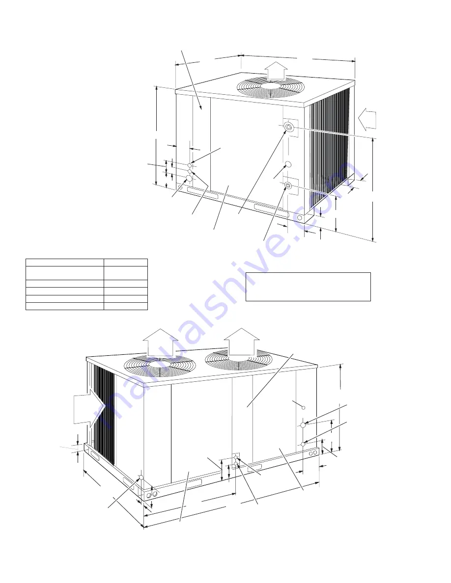
FIG. 4 - UNIT DIMENSIONS AND CLEARANCES

All dimensions are in millimeters and inches,
unless otherwise specified. They are subject
to change without notice. Certified
dimensions will be provided upon request.

AIR

OUT

AIR

IN

(117)

25-3/4

10-1/8

2-1/2

4-1/2

GUAGE 

LINE

ACCESS

(28.6) 1-1/8" OD

SUCTION LINE

(12.7) 1/2" OD

LIQUID LINE

COMPRESSOR AND 

CONDENSER FAN MOTOR

ACCESS

(22.2) 7/8: KNOCKOUT

ACCESSORY WIRING

ENTRY

(35) 1-3/8" DIA.

POWER WIRING

ENTRY

(22.2) 7/8" DIA.

CONTROL WIRING

ENTRY

32-1/2

5

CONTROL BOX

ACCESS

31-3/4

(1086)

(806)

42-3/4

4-5/8

(654)

(257)

(64)

(114)

(127)5

(50)2

(105)

4-1/8

(127)

(826)

AIR

OUT

AIR

IN

AIR

OUT

 (70)

2-3/4

(812)

  32

 (57)

2-1/4

 (825)

32-1/2

(1781)

70-1/2

(222)

8-3/4

(136)

5-3/8

CONTROL 

B

OX

ACCESS

GAUGE

LINE

ACCESS

(990)

  39

(28.6)

1-1/8 O

D


SUCTION LINE

(15.8)

5/8 O

D

LIQUI

D

 LINE

 (400)

15-3/4

(22.2) 7/8 

D

IA

CONTROL WIRING

ENTRY

COM

P

RESSOR AN

D


CON

D

ENSER FAN MOTOR

ACCESS

(34.9) 1-3/8 

D

IA.

P

OWER WIRING

ENTRY

(171)

6-3/4

CON

D

ENSER FAN MOTOR

ACCES

(22.2) 7/8" KNOCKOUT

ACCESSORY WIRING

ENTRY

(197)

.7-3/4

CLEARANCES (in. / mm)

Overhead (Top)

1

120" / 3048

Front
(Piping and Access Panels)

30" / 762

Left Side

24" / 610

Right Side

24" / 610

Rear

24" / 610

Bottom

2

0" / 0

1

Units must be installed outdoors. Overhanging structures or

shrubs should not obstruct condenser air discharge.

2

Adequate snow clearance must be provided if winter

operation is expected.

Summary of Contents for SUNLINE 2000 H4CE120

Page 1: ...eplacement parts on this equipment All forms may be ordered from Standard Register Toll Free Telephone 405 691 1126 Toll Free Fax 405 799 7746 INSPECTION As soon as a unit is received it should be inspected for possible damage during transit If damage is evident the extent of the damage should be noted on the carrier s delivery receipt A separate request for inspection by the carrier s agent shoul...

Page 2: ...nance 13 Cleaning Condenser Surface 13 Lubrication 13 Compressor Replacement 13 TABLES No Description Page 1 Unit Application Data 3 2 Physical Data 4 3 Electrical Data 5 4 Suction Lines 8 5 Liquid Lines 8 6 Refrigerant Line Charge 8 7 Cooling Capacities F 9 8 Cooling Capacities C 9 FIGURES No Description Page 1 Center of Gravity 3 2 Typical Rigging 4 3 Typical Field Wiring 5 4 Unit Dimensions and...

Page 3: ...ot be tied to the building foundation because noise and vibration will telegraph A unit can also be supported by concrete piers These piers should 1 extend below the frost line 2 be located under the unit s four corners and 3 be sized to carry the entire unit weight Refer to Figure 1 and Table 2 for the center of gravity and unit weight CAUTION Care should be taken to protect the unit from tam per...

Page 4: ... general installation procedure Refer to Figure 3 for typical field wiring COMPRESSOR Units are shipped with compressor mountings factory adjusted and ready for operation CAUTION Do Not loosen compressor mounting bolts COMPRESSOR CRANKCASE HEATER The compressor is equipped with a crankcase heater to pre vent refrigerant from mixing with crankcase oil during the OFF cycle The heaters will be energi...

Page 5: ...LECTRICAL DATA TABLE Unit Size MBH Compressor Condenser Fan Motor Total Unit Ampacity Amps Max Fuse Size1 Amps Power Supply RLA LRA Power Supply HP kW Each Qty FLA Each 090 380 415 3 50 17 3 111 220 240 1 50 3 4 56 1 2 9 22 3 30 120 380 415 3 50 19 6 118 220 240 1 50 1 2 37 2 2 1 26 2 35 1 Dual element 2 Based on three 60 C insulated copper conductors in steel conduit TABLE 3 ELECTRICAL DATA ...

Page 6: ...5 8 654 257 64 114 127 5 50 2 105 4 1 8 127 826 AIR OUT AIR IN AIR OUT 70 2 3 4 812 32 57 2 1 4 825 32 1 2 1781 70 1 2 222 8 3 4 136 5 3 8 CONTROL BOX ACCESS GAUGE LINE ACCESS 990 39 28 6 1 1 8 OD SUCTION LINE 15 8 5 8 OD LIQUID LINE 400 15 3 4 22 2 7 8 DIA CONTROL WIRING ENTRY COMPRESSOR AND CONDENSER FAN MOTOR ACCESS 34 9 1 3 8 DIA POWER WIRING ENTRY 171 6 3 4 CONDENSER FAN MOTOR ACCES 22 2 7 8 ...

Page 7: ...t charge The filter drier and is taped to the top of the compressor LINE SIZING When sizing refrigerant lines for a split system air conditioner check the following 1 Suction line pressure drop due to friction 2 Liquid line pressure drop due to friction 3 Suction line velocity for oil return and 4 Liquid line pressure drop due to static head NOTE Never base refrigerant line sizes on the OD of the ...

Page 8: ...2 F 1 1 C change in saturation temperature or approximately 3 psi 21 kPa sizing the lines for the proper return of oil is more important 5 These friction losses do not include any allowances for valves or fittings TABLE 4 SUCTION LINES 1 2 Unit Size MBH Refrigerant Flow Rate1 lbs kg per min Type L Copper Tubing in mm O D Refrigerant Gas Velocity ft m per min Pressure Drop3 Friction2 Vertical Rise ...

Page 9: ...cleaned before being used The liquid line connections can now be brazed while maintain ing a minimum flow of dry nitrogen through the piping as fol lows 1 Remove the cap from the 1 4 6mm access port on the liq uid line service valve 2 Connect a supply of dry nitrogen to this access port NOTE The filter drier and the moisture indicating sight glass should be installed in the liquid line as close to...

Page 10: ...n shipping position See FIG 6 2 Push the service ports through the corner post 3 Tighten the screws to secure the service ports for installa tion EVACUATION AND CHARGING Determine the required weight of refrigerant using Table 2 Physical Data and Table 6 Refrigerant Line Charge Table 2 includes operating charge based on the unit plus 25 feet of re frigerant lines Table 6 includes data required to ...

Page 11: ...035 15406 002 A 0504 Unitary Products Group 11 FIG 5 EXTENDING THE SERVICE PORTS ...

Page 12: ...stat must be OFF to prevent the compressor from starting CAUTION DO NOT ATTEMPT TO START THE COMPRES SOR WITHOUT AT LEAST 8 HOURS OF CRANK CASE HEAT OR COMPRESSOR DAMAGE WILL OCCUR Make sure that the bottom of the compressor is warm to the touch to prove crankcase heater operation PRE START CHECK Before starting the unit complete the following check list 1 Have sufficient clearances been provided ...

Page 13: ...control panel there are no capillary lines to be damaged 035 15406 002 A 0504 Unitary Products Group 13 MAINTENANCE CLEANING CONDENSER SURFACE Dirt should not be allowed to accumulate on the condenser coils or other parts in the condenser air circuit Clean as often as nec essary with a brush vacuum cleaner attachment or other suit able means SECURE OWNER S APPROVAL When the system is functioning p...

Page 14: ...14 Unitary Products Group 035 15406 002 A 0504 ...

Page 15: ...Unitary Products Group 15 035 15406 002 A 0504 ...

Page 16: ...ducts Group 5005 York Drive Norman Oklahoma 73069 Subject to change without notice Printed in U S A Copyright 2004 by Unitary Products Group All Rights Reserved 035 15406 002 A 0504 Supersedes 035 15406 001 B 0404 ...

Reviews: