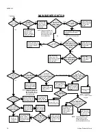
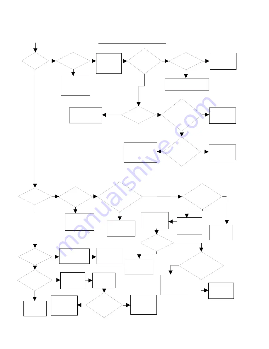
background image

Disconnect

sensor. Deenergize system.

Connect ohmmeter across sensor

and ground. Is resistance

less than 50

ohms?

No

Yes

Turn manual knob
on gas valve to OFF
position. Connect
manometer to outlet
pressure tap.

Does main

burner light?


Restore gas supply at
source. Energize system 
and check for proper
operation.

Turn manual knob on
gas valve to ON
position. Energize
system and check for
proper operation.

No

knob on gas valve

in ON position?

Purge system of air.
Energize system and
check for proper
operation.

No

Correct supply pressure. Energize
system and check for proper
operation.

No

Yes

Yes

Yes

Replace gas valve.
Energize system and
check for proper
operation.

Replace leads.
Energize system and
check for proper
operation.

Reset rollout switch.
Check wiring. If OK,
replace module. Energize
system and check for
proper operation.

NOTE: Diagnostic indicator may
           indicate one flash for "no 
           flame" condition. Inducer
           and circulator blower will   
           be on continuously.

NOTE:  Reset rollout switich.

No

Yes

Yes

Yes

No

No

No

Yes

No

No

Yes

NOTE: Diagnostic indicator may

           indicate one flash for "no 

           flame" condition. Inducer

           and circulator blower will   

           be on continuously.

No

Yes

Yes

Yes

No

No

Yes

No

Yes

No

Yes

Reconnect sensor

Disconnect electric
power to system at
main fuse or circuit
breaker.

Connect voltmeter 
from control 120 volt
hot line terminal
to ground.

Reposition flame
probe to achieve
1.0 m amp or make
flame current.

Check wiring. If OK,
replace module.
Energize system and
check for proper
operation.

Igniter remains heated
(bright red) with main
burner flame present.

Check wiring. If OK,
replace module.
Energize and check
for proper operation.

Reverse 120 V hot
and neutral line wires.

Less than 30 V

Unplug circulator
blower wires and
connect voltmeter
across terminals.

Disconnect electric
power to system at
main fuse or circuit
breaker.

System is
functioning
properly.

Check wiring. If OK,
replace module.
Energize the system
and check for proper
operation.

Replace circulator
blower connection.
Energize system at
main fuse or circuit
breaker.

NOTE:

To measure flame current,
disconnect sensor lead.
Connect microamp meter
in series with lead and sensor.

NOTE:

Flame probe
must be in flame
to sense.

Remove flame sensor.
Clean surface of flame
rod with fine steel wool
then reinstall.

Replace sensor.
Energize system and
check for proper
operation.

Continued

Is manual

MAIN BURNER IGNITION

Is gas

available at source?

Is outlet

pressure at nameplate

rating?

Disconnect

leads at gas valve.

Energize system. Is 25 V

present across MV & MV

module terminals after

warmup?

igniter

Turn

manual knob

on gas valve to ON.

Energize system. Is

outlet pressure

detected?

With

system energized

is 25 V present across

MV & MV terminals of

module after igniter

warm-up?

Does flame

sense probe have

carbon or dust

build-up?

 Is

ground wire

connected to furnace &

control box GND term.

wired to burner

ground?

Does

main burner

remain lit?

Correct ground

wiring.

Energize

the module and 

check for 120 v. 

Igniter

turns off with

main burner flame

present?

Is

flame probe

located properly in flame?

Proper location will provide

adequate flame

current.

Energize

the module and

check for 120 v across

terminals circulator

heat & Cir

neutral?

Does

the circulator

blower energize at heat

speed within 1 min?

Main burner

on.

650.69-N3

18

Unitary Products Group

Summary of Contents for P2MP Series

Page 1: ...s supplier s instructions If you cannot reach your gas supplier call the fire department IAMON 80 D D UPFLOW MULTI POSITION GAS FIRED FURNACES INDUCED DRAFT STYLE G INSTALLATION INSTRUCTION Supersedes...

Page 2: ...ired appli ances as allowed by the National Fuel Gas Code NFPA 54 ANSI Z223 1 latest edition WARNING This appliance is not to be used for temporary heating of buildings or structures under constructio...

Page 3: ...pace The openings shall com municate freely with interior areas having adequate infil tration from the outside NOTE At least 100 square inches free area shall be used for each opening 2 Air Source fro...

Page 4: ...2MPD20 11201 35 65 180 3 4 11 x 10 13 8 15 14 16 X 25 25 X 27 163 Variable Speed Blower Models P2MPV12N06401 25 55 180 1 2 10 x 7 12 15 14 16 X 25 16 X 27 119 P2MPV14N08001 30 60 180 1 2 10 x 9 12 15...

Page 5: ...3 8 15 14 2 14 X 20 168 Model designator may be N for standard units or L for factory built low NOx units Model A B C D P2DPD10 04801 16 1 4 14 15 3 P2DPD12 06401 16 1 4 14 15 4 P2DPD12 08001 22 1 4 2...

Page 6: ...al Fuel Gas Code ANSI Z223 1 or the CAN CGA B149 Installation Codes and these in structions Determine that there is no blockage or restric tion leakage corrosion or other deficiencies which could caus...

Page 7: ...ilter and Mounting System A return air filter grille or duct mounted filter may be provided The following minimum sizes are recom mended NOTE Air velocity through throw away type filters may not excee...

Page 8: ...ing rod pipe or straps refer to Physical Data Page 4 for furnace weights to determine suitable means of suspension Angle supports should be placed at the supply air end and near the blower deck Units...

Page 9: ...ied on the rating plate or a matching cooling coil Follow the instructions with the combustible floor base acces sory The floor opening dimensions for the floor base are shown in Figure 10 This base c...

Page 10: ...with the provisions of the National Electrical Code ANSI NFPA No 70 latest edition Canadian Electric Code C22 1 Part 1 latest edition and or local codes Electrical wires which are field installed shal...

Page 11: ...t rely upon the interlock switch as a main power disconnect Rollout Switch Controls These controls are mounted on the burner assembly If the temperature in the burner compartment exceeds its set point...

Page 12: ...t is not within 2 of the furnace rating with allowance being made for the permissible range of the regula tor setting 0 3 inches W C replace the orifice spuds with spuds of the proper size CAUTION Be...

Page 13: ...use the same speed tap for heating and cooling the heat terminal and cool terminal must be connected using a jumper wire and connected to the desired motor lead Place all unused motor leads on Park t...

Page 14: ...l begin and the burner will operate normally if the gas supply returns or the fault condition is corrected prior to the last ignition attempt Otherwise the control will lockout The control will repeat...

Page 15: ...n Start the system by setting the thermostat above room temperature Observe the system s response Then use the Troubleshooting tables in this manual to check the system s operation Use the troubleshoo...

Page 16: ...tat G to R contacts close FAN ONLY CHECK COOLING CYCLE CHECK Does the circulator blower energize at cool speed Is 25 volts present across terminals Y C Is 25 volts present across terminals R C Is 25 v...

Page 17: ...or circuit breaker System is functioning properly Connect voltmeter across terminals of igniter harness Check wiring If ok replace thermostat Energize system and check for proper operation No No Yes...

Page 18: ...esent Check wiring If OK replace module Energize and check for proper operation Reverse 120 V hot and neutral line wires Less than 30 V Unplug circulator blower wires and connect voltmeter across term...

Page 19: ...WIRING DIAGRAM UPFLOW MULTI SPEED MODELS NOTE The furnace s control system depends on correct polarity of the power supply 650 69 N3 Unitary Products Group 19...

Page 20: ...WIRING DIAGRAM DOWNFLOW MODELS NOTE The furnace s control system depends on correct polarity of the power supply 650 69 N3 20 Unitary Products Group...

Page 21: ...2110 2004 1913 1797 1581 MED 2027 1986 1945 1917 1877 1820 1763 1653 1558 1445 LOW 1349 1327 1312 1281 1233 1150 1078 P2MPD20N11201 See Notes 6 7 HIGH 2204 2154 2081 2055 2002 1933 1843 1706 1545 1409...

Page 22: ...PD16 08001 HIGH 2043 2000 1893 1823 1726 1627 1503 1382 1249 1134 MED 1706 1655 1593 1533 1450 1366 1265 1163 1062 950 LOW 1452 1406 1373 1317 1245 1174 1112 1025 935 817 P2DPD16 09201 HIGH 2053 1977...

Page 23: ...NOTES 650 69 N3 Unitary Products Group 23...

Page 24: ...y Products Group P O Box 1592 York Pennsylvania USA 17405 1592 Subject to change without notice Printed in U S A Copyright by York International Corporation 1994 All Rights Reserved Code SBY 650 69 N3...

Reviews: