9. Reinstall the blower assembly. Replace mounting screws
that hold the blower assembly to the front portion of the
blower deck. Two mounting screws used on the sides of
the blower are used for shipping purposes only, and are
not necessary after the furnace has been installed.
10. Reinstall the control box and reconnect the wiring harness
plugs.
11. Replace the access doors and restore the electrical supply
to the unit.
Burner Removal/Cleaning
The main burners should be checked periodically for dirt
accumulation.
If cleaning is required, follow this procedure:
1. Turn off the electrical power to the unit.
2. Remove the access door.
3. Remove the igniter.
4. Turn off the gas supply at the external manual shutoff valve
and loosen the ground union joint.
5. Remove the airshield.
6. Remove the four screws that hold the burner assembly to
the vest panel and remove the assembly.
7. Remove burners from the burner assembly.
8. Burners may be cleaned by rinsing in hot water.
9. Reassemble the burners in the reverse order, making sure
the burner shield is tightened securely in place.
Cleaning the Heat Exchanger
1. Turn off the main manual gas valve external to the furnace.
2. Turn off electrical power to the furnace.
3. Remove the upper access door and remove airshield
4. Disconnect wires from HSI sensor, rollout switch and HSI
igniter. Remove igniter carefully, as it is easily broken.
5. Remove the screws that hold the burner assembly to the
vestibule panel and remove the assembly. The lower
portion of the heat exchanger will now be exposed.
6. Remove inducer blower and motor at the top of the fur-
nace. Remove upper plate.
7. The upper portion of the heat exchanger is now exposed.
8. With a long flexible wire brush, clean inside each tube at
both the top and bottom. The brush must pass around the
rear heat exchanger tubes. Vacuum loose scale and dirt
from each tube.
9. Clean - vacuum all burners.
10. Replace all components in reverse order. Reconnect all
wiring.
11. Restore electrical power and gas supply to the furnace.
12. Check furnace operation.
TROUBLESHOOTING
The following visual checks should be made before trou-
bleshooting:
1. Check to see that the power to the furnace and the ignition
control module is ON.
2. The manual shutoff valves in the gas line to the furnace
must be open.
3. Make sure all wiring connections are secure.
4. Review the sequence of operation.
Start the system by setting the thermostat above room
temperature. Observe the system’s response. Then use the
Troubleshooting tables in this manual to check the system’s
operation.
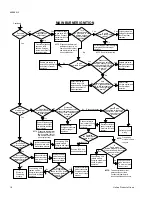
Use the troubleshooting table by reading the upper left-hand
box and then following the instructions in each box. If the
condition described in the box is true (yes answer), go down to
the next box. If the condition is not true (no answer), go to the
box to the right.
Continue checking and answering the questions in the boxes until
the problem is explained and corrective action is described. After
any maintenance or repair, the troubleshooting sequence can be
repeated until normal system operation is obtained.
FURNACE CONTROL DIAGNOSTICS
The furnace has built-in, self diagnostic capability. If a system
problem occurs, a fault code is shown by a blinking LED on the
blower deck. It is located just to the right of the wiring harness
plug. To view the LED, remove the top furnace panel. DO NOT
remove the furnace blower compartment panel OR turn off
furnace power as either action will clear the control’s memory
of the fault.
The control continuously monitors its own operation and the
operation of the system. If a failure occurs, the LED will indicate
the failure code. If the failure is internal to the control, the light
will stay on continuously. In this case, the entire control should
be replaced as the control is not field repairable.
If the sensed failure is in the system (external to the control),
the LED will flash in the following flash-pause sequences to
indicate failure status (each flash will last approximately 1/4
second, each pause will last approximately 2 seconds).
1 flash, then pause........
System lockout
2 flashes, then pause ....
Pressure switch stuck closed
3 flashes, then pause ....
Pressure switch stuck open
4 flashes, then pause ....
Open high limit switch
5 flashes, then pause ....
Open rollout switch
Continuous flashing
(no
pause)..............
Flame has been sensed when
no
flame
should
be
present
(no
call
for
heat)
LED on -not flashing......
Faulty control
The LED will also flash once at power-up. If the control is locked
out, it may be reset by momentary power interruption. Either
the 24v thermostat or line voltage may be interrupted for 30
seconds or longer.
WARNING: Never jump pressure switch to allow furnace op-
eration. To do so will allow furnace to operate under
potentially hazardous conditions.
WARNING: Do not try to repair controls. Replace defective
controls with UPG Source 1 Parts.
WARNING: Never adjust pressure switch to allow furnace
operation.
650.69-N3
Unitary Products Group
15


