106306-UUM-A-0205
Unitary Products Group
11
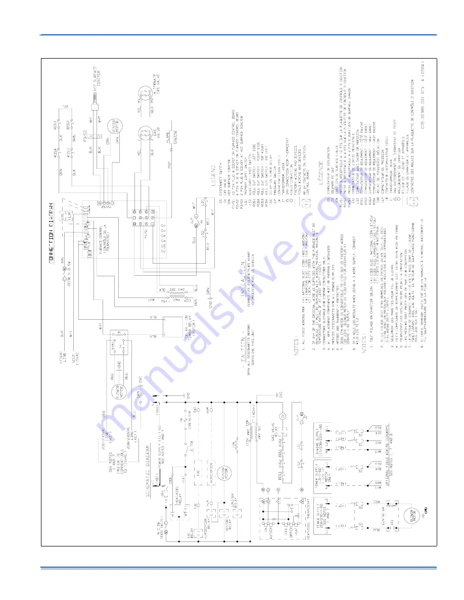
SECTION IV: WIRING DIAGRAM
FIGURE 12:
Wiring Diagram
Page 1: ...ts that have been wet or the furnace if deemed necessary FIRE OR EXPLOSION HAZARD Failure to follow safety warnings exactly could result in serious injury death or prop erty damage Do not store or use...
Page 2: ...furnace casing making sure the physical support is sound without sagging cracks or gaps Examine the furnace base making sure it is physically sound without cracks gaps or sagging and has a good seal...
Page 3: ...Read the safety information above 2 Set the thermostat to the lowest setting 3 Turn off all electric power to the appliance 4 Remove furnace door 5 Move gas control switch to the OFF position Do not f...
Page 4: ...th air filters Table 1 will indicate 2 filters by using brackets with the number two 2 2 After you determine the cabinet size and what return configuration you have look up the recommended filter size...
Page 5: ...f the motor and wheel are heavily coated with dust they can be brushed and cleaned with a vac uum cleaner If the blower cannot be properly cleaned without removing it from the furnace then this servic...
Page 6: ...tor plate assem bly to the vestibule panel The surface is also gasketed The assembly including the flue baffle plate rear may be vacuumed or cleaned with hot water if necessary 3 The upper portion of...
Page 7: ...ated the number of times equal to the code For example six on flashes equals a number 6 fault code All flash code sequences are broken by a 2 sec ond off period SLOW GREEN FLASH Normal operation SLOW...
Page 8: ...CODE STORAGE AND RETRIEVAL The control in this furnace is equipped with memory that will store up to five error codes to allow a service technician to diagnose problems more easily This memory will be...
Page 9: ...ucts Group 9 SECTION III REPLACEMENT PARTS LIST NEUTRALS EAC COOL HEAT HUM PARK PARK L1 XFMR Y W R G C 37 36 28 43 46 2 25 9 4 45 7 33 38 34 8 15 1 16 32 5 27 6 3 39 22 23 18 31 14 35 29 10 47 41 44 1...
Page 10: ...R N Model PLATE RESTRICTOR L Model Style C PLATE RESTRICTOR L Model Style D 38 COLLAR FLUE 39 HANDLE DOOR 40 GASKET RESTRICTOR PLATE 41 TUBING SILICONE 42 SPRING DOOR 43 DIAGRAM WIRING 44 HARNESS WIRI...
Page 11: ...106306 UUM A 0205 Unitary Products Group 11 SECTION IV WIRING DIAGRAM FIGURE 12 Wiring Diagram...
Page 12: ...nly to products installed in the United States and Canada EXCLUSIONS This warranty does not cover any 1 Shipping labor or material charges 2 Damages resulting from transportation installation or servi...