


515.28-N3Y
Unitary Products Group
9
REFRIGERANT LINE CHARGES
The outdoor condensing unit may be connected to the indoor
evaporator coil using field supplied refrigerant grade copper
tubing that is internally clean and dry. Units should be
installed only with the tubing sizes for approved system com-
binations as specified in Tabular Data Sheet. The charge
given is applicable for total tubing lengths up to 15 feet. See
Application Data Form 690.01-AD1V for installing tubing of
longer lengths and elevation differences.
NOTE:
Using a larger than specified line size could result in
oil return problems. Using too small a line will result in loss of
capacity and other problems caused by insufficient refriger-
ant flow. Slope horizontal vapor lines at least 1" every 20 feet
toward the outdoor unit to facilitate proper oil return.
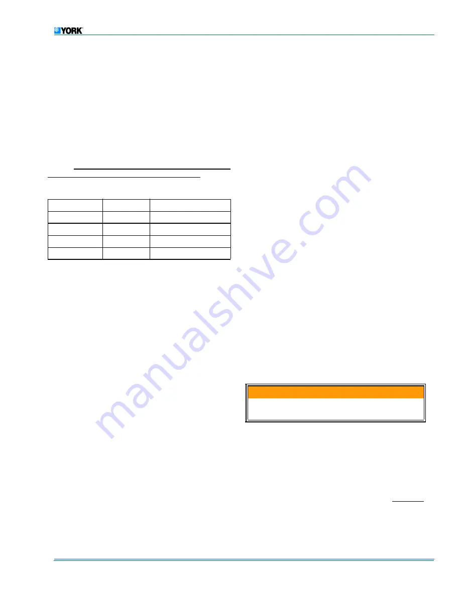
Sweat connect units also include sufficient charge for 15 feet
of lines. Table 2 lists the refrigerant line charges.
The “TOTAL SYSTEM CHARGE” must be permanently
stamped on the unit data plate.
Total system charge is determined as follows:
1.
Determine outdoor unit charge from tabular data sheet.
2.
Determine indoor coil adjustment from tabular data
sheet.
3.
Calculate the line charge with the factors in Table 2 for-
sweat lines in excess of 15 ft.
NOTE:
The line charge over 15 feet should be included on the-
data plate and must be added to the system.
4.
Total system charge = item 1 + item 2 + item 3.
5.
Permanently stamp the unit data plate with the total
amount of refrigerant in the system.
USE THE FOLLOWING CHARGING METHOD WHENEVER
ADDITIONAL REFRIGERANT IS REQUIRED FOR THE
SYSTEM CHARGE.
Measurement Method
A calibrated charging cylinder or accurate weighing device
must be used to add refrigerant. This is the only accurate
charging method for heat pumps in the heat pump mode.
Check flare caps on service ports to be sure they are leak
tight. DO NOT OVERTIGHTEN (between 40 and 60 inch-lbs.
maximum).
Superheat Charging Method
NOTE:
Use this method only during system maintenace and
repair
1.
Operate system until temperatures and pressures stabi-
lize (minimum of 10 minutes).
2.
Measure and record indoor wet bulb (WB) temperature
using a sling psychrometer and the outdoor dry bulb
(DB) temperature using a thermometer.
3.
Measure and record the suction pressure at the suction
service valve port.
4.
Using Table 3, note the superheat value corresponding
to the intersection of the indoor wet bulb and the outdoor
dry bulb.
5.
With the superheat value obtained in step 4 and the suc-
tion pressure value from step 3, find the intersection of
the values in Table 4. This is the required suction tube
tempera-ture at the suction service valve.
6.
To bring the tube temperature in line with the required
value from Table 4, add refrigerant to the service port to
cause the tube temperature to fall and reclaim refrigerant
to cause the temperature to rise.
Check flare caps on Schrader fittings to be sure they are
tight. DO NOT OVERTIGHTEN (40-60 inch-lbs. maximum).
SYSTEM START-UP
ENERGIZE CRANKCASE HEATER
This unit is equipped with a crankcase heater for the com-
pressor.
A warning label with an adhesive back is supplied in the unit
installation instruction packet. This label should be attached
to the field supplied disconnect switch where it will be easily
seen. See below.
In order to energize the crankcase heater:- Set indoor two
stage cooling thermostat to "OFF" position.- Close the line
power disconnect to the unit.
SYSTEM OPERATION
See Figure 8 to trace the flow of refrigerant through the sys-
tem.
WITH POWER TO UNIT AND THERMOSTAT IN
COOLING
POSITION.
1.
Reversing valve is energized through thermostat system
switch to position refrigerant circuit for cooling operation.
In the cooling cycle, discharge gas is pumped to the out-
Table 2: REFRIGERANT LINE CHARGES
LIQUID OD
VAPOR OD
R-22 CHARGE OZ./FT.
3/8"
5/8"
0.66
3/8"
3/4"
0.68
3/8"
7/8"
0.70
3/8"
1-1/8"
0.76
IMPORTANT
An attempt to start the compressor without at least 8
hours of crankcase heat will damage the compressor.


