


Appendix
Troubleshooting
66
GLOBAL
INDUSTRIES, INC.
Drag Conveyors
10230011
2016-06-14
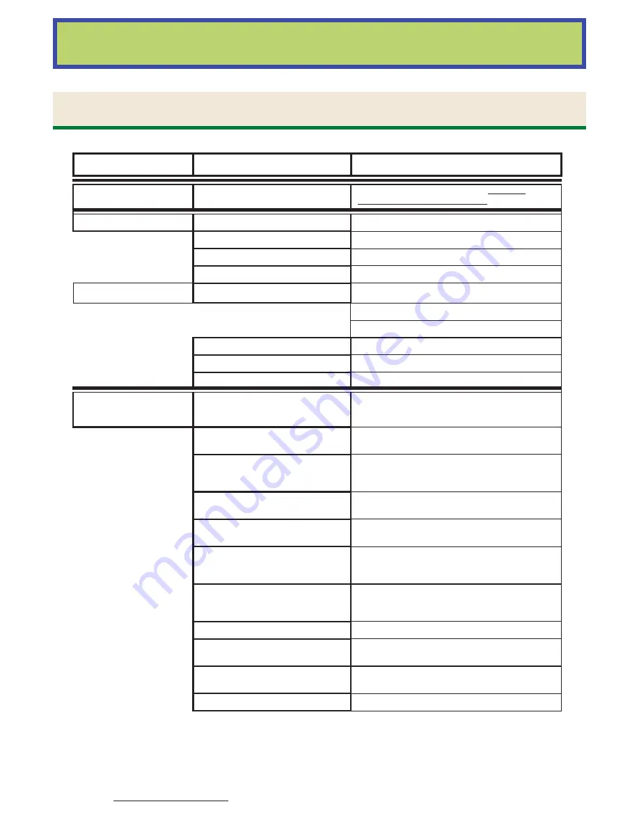
chain
premature chain
and sprocket wear
chain not installed correctly
install new chain as required; see the chain
installation section of this manual.
motor
can’t start chain
motor rotation reversed
wired wrong / wire correctly
conveyor fi lled with material
material not shut off while conveyor was stopped
damaged reducer
broken gears or bearings / replace them
paddle caught in conveyor
loosen the paddle
motor
starter kicking out
motor overloaded
conveyor overloaded adjust load
line voltage low
wrong drive sheaves
motor too small
current draw excessive
starter not sized to motor
heaters wrong size
motor/starter device defective
fi x or replace
noise
and/or vibration
excessive
drive and take-up tail sprockets
aren’t centered on the shaft. (correct
as soon as possible)
set screws may have been loose or it may have
been improperly installed / adjust the sprocket to
center and make certain set screws are tight.
conveyor chain tension is not correct
the chain tension is either too loose or too tight /
adjust it
check chain and paddles for damage
from foreign object caught in
conveyor
remove foreign object and replace parts as needed
check for loose or missing hardware
or paddles
check for and replace any missing bolts or paddles
motor, reducer, or bearing noise is
excessive
faulty motor, reducer, or bearing / check oil levels,
shaft seals, and drive components - fi x as needed
dents, punctures, bowed panels, or
bowed lids are hindering conveyor
fl ow
repair or replace any damaged parts
the noise is originating from
equipment interfacing with the
conveyor
check auxiliary equipment and make any needed
repairs
noise at fl anges
trough out of alignment / adjust alignment
wear in bearings
abrasive in oil produce wear / replace worn
bearings; fl ush drive and replace oil
excessive speed
check specifi cations and alter drive settings to
proper speed
low oil level
reduced muffl ing effect of the oil / add oil
Trouble
Problem
Cause / Solution