<6. PROCEDURES FOR CONVERTER OPERATION>
6-17
IM 12E04A02-02E
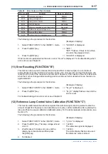
Table 6.8 Error Codes and Their Contents
Error code
Contents
Mode for detection
Err11
Turbidity overrange
MEAS.
Err12
Lamp voltage error
MEAS.
Err13
Lamp disconnection
MEAS.
Err14
A/D circuit error
Any mode
Err15
Memory comparison error Any mode
Any mode
Err18
Reference signal voltage error
MEAS.
Err25
Service life of lamp
MEAS.
Err26
Automatic zero-calibration error
MEAS.
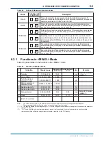
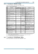
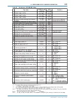
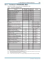
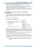
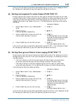
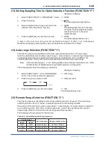
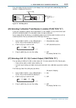
The following is the procedure for this function.
(Example of display)
1. Select FUNCTION "A" in the <MAINT.> mode.
=> "E.CHEC" is displayed.
2. Press the [ENT] key.
=> "Err11"
"Err11"
fl
ashes. If there is more than
one error, they appear in turn.
3. Press the [ENT] key.
=> "E.CHEC" is displayed.
If this function is operated when there is no error, "Good" is displayed. For troubleshooting when
errors occur, see Chapter 8.
(11) Error Resetting (FUNCTION "B")
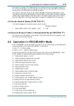
This function can reset error statues (FAIL lamp and FAIL contact output). An error status is
automatically reset at an instance when the causes of an error are removed but this function can
reset the error even if the causes are not removed. However, if the causes of the error still remain
when the mode is changed after resetting and moved to each error detection mode, that error is
again detected.
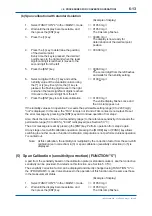
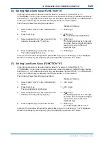
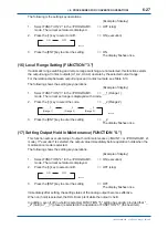
The following is the procedure for this function.
(Example of display)
1. Select FUNCTION "B" in the <MAINT.> mode.
=> "CL_Er" is displayed.
2. Press the [ENT] key.
=> "CL_Er" display
fl
ashes once and the
error is reset.
For troubleshooting when errors occur, see Chapter 8.
(12) Reference Lamp Control Valve Calibration (FUNCTION "C")
This function determines the reference signal of the reference light-receiving element when the
amount of light from the lamp is controlled. Be sure to carry out this calibration after replacing the
lamp and then do a span calibration (calibration plate). For the lamp replacement procedure, see
Section 7.5.
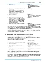
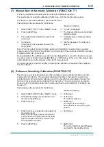
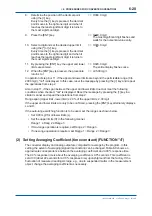
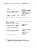
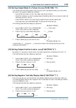
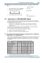
The following is the procedure for this function.
(Example of display)
1. Select FUNCTION "C" in the <MAINT.> mode.
=> "L_CAL" is displayed.
2. Press the [ENT] key. The lamp voltage is
fi
xed
=> 1.4203 V
at 4.3 V.
The reference signal is displayed.
3. Wait for about 5 minutes or more until the
=> 1.4203 V
display becomes stable and then press
The entire display
fl
ashes once and
the [ENT] key.
the reference value is stored.
4. Terminated.
3rd Edition : May. 31, 2010-00
Summary of Contents for Vigilant Plant EXA TB Series
Page 49: ...Blank Page ...
Page 59: ...Blank Page ...
Page 119: ...Blank Page ...
Page 125: ...Blank Page ...
Page 127: ...Blank Page ...
Page 133: ...Blank Page ...

