17-10
IM 05P04D41-01EN
17.4.5 Contact Output Wiring
CAUTION
1) Use an auxiliary relay for load-switching if the contact rating is exceeded.
2) Connect a bleeder resistor when a small current is used, so that a current
exceeding 1 mA can be supplied.
3) The output relay has a limited service life. Be sure to connect a CR filter (for AC)
or diode (for DC) to the load.
4) If there is a risk of external lightning surges, use a lightning arrester etc.
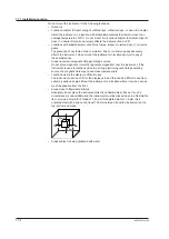
5) Since the insulation provided to each relay output terminal is Functional
insulation, provide Reinforced insulation to the external of the device as
necessary. (Refer to the drawing below.)
This product
Functional
insulation
A safety
voltage circuit
A safety
voltage circuit
This product
Reinforced insulation
Reinforced insulation
Functional
insulation
A hazardous
voltage circuit
A hazardous
voltage circuit
A safety
voltage circuit
A safety
voltage circuit
This product
Reinforced insulation
Reinforced insulation
Functional
insulation
A hazardous
voltage circuit
A hazardous
voltage circuit
A hazardous
voltage circuit
A hazardous
voltage circuit
► When using auxiliary relay: 17.4.3 Limit Control Output (Relay) Wiring
UT35A-L
Contact Output Equipped as Standard
Relay contact
AL3
AL2
AL1
COM
COM
COM
Contact rating: 240 V AC, 1 A
30 V DC, 1 A (resistance load)
104
105
106
107
108
109
ALM
The following table shows the initial status.
AL1 terminal
AL2 terminal
AL3 terminal
Alarm 1
(PV high limit)
Alarm 2
(PV low limit)
Alarm 3
(PV high limit)
17.4 Wiring
Summary of Contents for UT35A-L
Page 3: ......
Page 15: ...Blank Page...
Page 25: ...Blank Page...
Page 39: ...Blank Page...
Page 59: ...Blank Page...
Page 91: ...Blank Page...
Page 105: ...Blank Page...
Page 147: ...Blank Page...
Page 149: ...Blank Page...


