


1-4
<Toc>
<1. Installation>
IM 05F01D02-41E
1st Edition : May 31,2000-00
■
How to Install
CAUTION
Turn off the power to the indicator before installing it on the panel because there is a possi-
bility of electric shock.
After opening the mounting hole on the panel, follow the procedures below to install the
indicator:
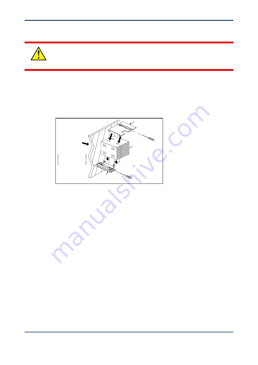
1.
Insert the indicator into the opening from the front of the panel so that the terminal
board on the rear is at the far side.
2.
Set the brackets in place on the top and bottom of the indicator as shown in the figure
below, then tighten the screws of the brackets. Take care not to overtighten them.
Large bracket
(top mounting hardware)
Terminal board
Small bracket
(bottom mounting hardware)
Panel
Insert a screwdriver into the
brackets to tighten the screws.
Direction to insert the
indicator
Insert the indicator
into the opening at
the front of the panel.
Note: Right and left mounting for UM330.
Summary of Contents for UM330
Page 2: ...Blank Page ...
Page 6: ...Blank Page ...
Page 20: ...Blank Page ...
Page 32: ...Blank Page ...
Page 48: ...Blank Page ...
Page 50: ...Blank Page ...