background image

IM 12B6K3-E-E

5

* Note: 

The insertion depth of the probe is given in the dimensional drawing.

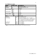
Model

Suffix code

Description

PR20

Retractable fitting

Material

-S

Stainless steel AISI 316

-T

Titanium

Probe length*)

-05 

0.5 mtr.

-10

1 mtr.

Cable length

-05

5 mtr.

-10

10 mtr.

Temp. sensor

-T1

Pt1000

-T2

Pt100

Style

*B

Style code

Adapters

/YYY See separate table

Certificates

/M

Material certificate 3.1B according to 
EN-10-024 (DIN 50049) on wetted partsa

/T

Test certificate for hydrostatic pressure 
test (2 MPa at ambient temperature)

Combined

/EB

SC21-AAP26

electrode

/EG

SC21-AGP24

/EH

SC21-AGP25

2-4. Model and codes

Summary of Contents for PR20

Page 1: ...IM 12B6K3 E E 9th Edition User Manual Model PR20 Retractable fitting for combined pH redox electrodes ...

Page 2: ...IM 12B6K3 E E ...

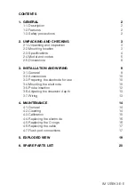
Page 3: ...s 8 3 INSTALLATION AND WIRING 9 3 1 General 9 3 2 Accessories 10 3 3 Preparing the electrode for use 10 3 4 Mounting the electrode 10 3 5 Probe insertion 12 3 6 Adjusting the iinsersion depth 13 3 7 Wiring 13 4 MAINTENANCE 14 4 1 General 14 4 2 Cleaning 14 4 3 Calibration 15 4 4 Replacing the electrode 16 4 5 Replacing the O rings 16 4 6 Replacing the cable 17 4 7 Flush port connections 17 5 EXPLO...

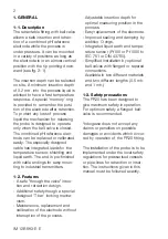
Page 4: ...ing to industrial transmitters 1 2 Features A safe through the valve inser tion and retraction design Additional safety though a special designed T bar locking mecha nism Maintenance replacement and calibration of the electrode without interruption of the process Adjustable insertion depth for optimal measuring position in the process Easy replacement of the electrode Improved sealing and damping ...

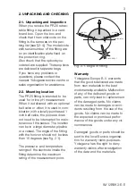
Page 5: ...ard board box Open the box and check that the model code on the fitting is the same as on the pac king list see 2 4 The model code with serial number of the fitting are on an identification plate fixed on the protection ring Also check that the options you ordered are supplied These options are delivered in separate bags If you have any problems or questions please contact the nearest Yokogawa ser...

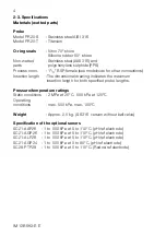
Page 6: ...ndicates the maximum insertion length for both specified probe lengths Pressure temperature ratings Static conditions 2 MPa at 20 C 500 kPa at 125 C Operating conditions max 500 kPa max 100 C Weight Approx 2 5 kg SS316 version without ball valve Specification of the optional senors SC21 AAP26 1 to 500 kPa at 0 to 110 C pH ref electrode SC21 AGP26 1 to 500 kPa at 0 to 110 C pH ref electrode SC21 AL...

Page 7: ...robe length 05 0 5 mtr 10 1 mtr Cable length 05 5 mtr 10 10 mtr Temp sensor T1 Pt1000 T2 Pt100 Style B Style code Adapters YYY See separate table Certificates M Material certificate 3 1B according to EN 10 024 DIN 50049 on wetted partsa T Test certificate for hydrostatic pressure test 2 MPa at ambient temperature Combined EB SC21 AAP26 electrode EG SC21 AGP24 EH SC21 AGP25 2 4 Model and codes ...

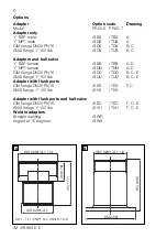
Page 8: ...N25 PN16 SDS TDS B C ANSI flange 1 150 lbs SUS TUS B C Adapters and ball valve 1 BSP female SBB TBB A D 1 NPT female SNN TNN A D DIN flange DN25 PN16 SDD TDD B C E ANSI flange 1 150 lbs SUU TUU B C E Adapter with flush ports DIN flange DN25 PN16 SES TES F C ANSI flange 1 150 lbs SVS TVS Adapter with flush ports and ball valve DIN flange DN25 PN16 SED TED F C E ANSI flange 1 150 lbs SVU TVU F C E W...

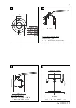
Page 9: ...ø42 5 ø79 2 ø15 7 1 inch 95 3 75 125 4 9 65 2 56 23 0 90 ISO 229 1 G 1 1 4 63 2 55 F E D C Internal thread both sides ISO 228 1 G 1 OR 1 11 1 2 NPT ACC ANSI B 1201 Glanges both sides DN25 PN10 acc DIN 2642 or 1 150Lbs acc ANSI B 16 5 1 8 27 NPT vlg ANSI G 1 20 1 ...

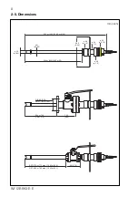
Page 10: ...1 3 ø 55 ø 2 16 240 9 45 ø 23 ø 0 90 390 or 890 15 35 or 35 550 or 1050 21 65 or 41 35 200 or 700 7 9 or 27 5 DIN 85 3 35 ANSI 79 4 3 125 125 4 95 BSP 275 or 775 max 10 85 or 30 5 NPT 265 or 765 max 10 45 or 30 1 95 3 75 ø 48 ø 1 9 ø 21 ø 0 83 mm inch ...

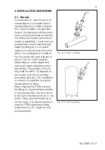
Page 11: ...nance and calib ration For maintenance or calibra tion the probe will need a space of about 2 mtr for total retraction depending on probe length and optional process adapters and or ball valves The position of the fit ting must be within 15 degrees of the horizon with the tip pointing downward see fig 2 1 Installation in a bend of a pipe line is a good measurement position When inserting the PR20 ...

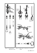
Page 12: ...30 in the exploded view ATTENTION Do not insert the fitting into the pro cess without the electrode moun ted Prevent liquid to come into contact with the connector plug Start with the assembly of the elec trode into the probe and follow the instructions for the preparation of a new electrode see 3 3 3 2 Accessories Optional accessories are delivered separately When a ball valve is ordered as an op...

Page 13: ...1 Unscrew the pigtail One will hear clicking Move the pigtail Move the plug in connector Move the cable figure 3 3 preparing the electode for use Turn thight Press figure 3 4 Mounting the electrode in the PR20 fitting ...

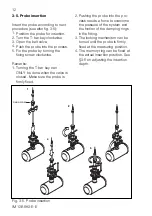
Page 14: ...asuring position 4 The memory ring can be fixed at the actual insertion position See 3 6 on adjusting the insertion depth 3 5 Probe insertion Insert the probe according to next procedure see also fig 3 5 1 Position the probe for insertion 2 Turn the T bar key clockwise 3 Open the ball valve 4 Push the probe into the process 5 Fix the probe by turning the fixing screw clockwise Remarks 1 Turning th...

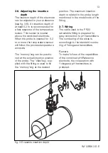
Page 15: ...io ned at the actual insertion position of the probe The Allan key sup plied with the fitting is used to fix the memory ring at the desired fig 3 6 variable insertion depht position The maximum insertion depth is related to the probe length mentioned in the model code of the fitting 3 7 Wiring The cable used in the PR20 retractable fitting is prepared for easy connection to pH transmitters The num...

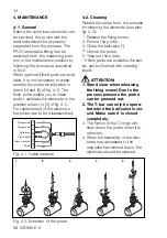
Page 16: ...e in the position shown in 3 of fig 4 2 For replacement of the electrode the probe has to be disassembled 4 2 Cleaning Retract the probe from the process for cleaning the electrode see also fig 4 2 1 Release the fixing screw 2 Pull out the probe 3 Close the ball valve 4 Unlock the probe 5 Take out the probe If flush ports are available the sen sor can be flushed with cleaning liquid ATTENTION 1 St...

Page 17: ...i de KCl solution and letting it cool to room temperature After cleaning the probe is re inser ted into the process by following the reverse procedure see 3 5 4 3 Calibration It is recommended to start calibra tion with a clean electrode Always calibrate a new electrode With the electrode connected to the transmitter a calibration can take place Check the appropriate chap ters in the instruction m...

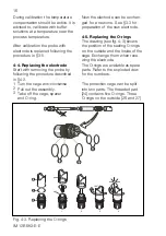
Page 18: ...dure described in 4 2 1 Turn the cage anti clockwise 2 Pull out the assembly 3 Take off the cage spacer and O ring Now the electrode can be exchan ged for a new one See 3 3 for preparation of the new electrode 4 5 Replacing the O rings The drawing see fig 4 3 shows the position of the sealing O rings on the outside and the inside of the cage Exchange them when rene wing the electrode The O rings a...

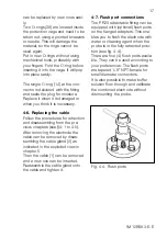
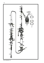
Page 19: ...sembling from the pre vious chapters see 4 1 to 4 5 After removing the electrode the cable can be removed by disas sembling the cable gland 2 as indicated in the exploded view in chapter 5 Then the cable 1 can be removed and a new one can be inserted Reassemble the cable gland onto the cable and tighten it 4 7 Flush port connections The PR20 retractable fitting can be equipped with optional flush ...

Page 20: ...IM 12B6K3 E E 18 ...

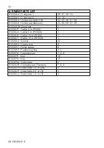
Page 21: ...12 Protection ring 13 Inner tube 14 O ring Viton 70 shore 12x1 15 T bar with key 16 Nut 17 Fixing screws 2 pcs 18 Chamber 19 O ring Viton 70 shore 29 7 x 3 5 20 Adapter optional 21 Ball valve optional 22 Combined pH reference electrode 23 Spacer 24 Electrode holder 25 Protection sleeve 26 O rings 2 pcs Viton 70 shore 15 6 x 1 78 27 O ring Viton 70 shore 17 12 x 2 62 28 O rings 2 pcs Viton 70 shore...

Page 22: ... K1520LP Cable 5 m Pt100 1 K1520LQ Cable 5 m Pt1000 1 K1520LS Cable 10 m Pt100 1 K1520LT Cable 10 m Pt1000 1 K1520AZ Spacer 23 K1520KD Clamp ring 8 K1520KC Fixing screw 6 K1520KF Positioning ring 4 5 K1520TA Clamping set 7 8 9 K1520TF Nut 16 K1520TK Key 15 K1520TN Outer tube 3 K1520UB Clamping set Titanium 7 8 9 K1520UH Outer tube 1 0 m SS 3 K1520UF Outer tube 0 5 m Ti 3 K1520UJ Outer tube 1 0 m T...

Page 23: ...IM 12B6K3 E E 21 ...

Page 24: ...el 1 770 253 7000 Fax 1 770 251 2088 E mail info yca com www yokogawa com us YOKOGAWA ELECTRIC ASIA Pte Ltd 5 Bedok South Road Singapore 469270 Singapore Tel 65 241 9933 Fax 65 241 2606 E mail webinfo yas com sg www yokogawa com sg YOKOGAWA HEADQUARTERS 9 32 Nakacho 2 chome Musashinoshi Tokyo 180 Japan Tel 81 422 52 5535 Fax 81 422 55 1202 E mail webinfo mls yokogawa co jp www yokogawa co jp Yokog...

Reviews: