IM 12B6K3-E-E
9
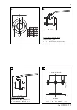
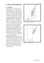
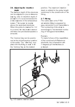
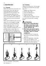
Fig. 3-1a. Pipe mounting
Fig. 3-1b. Tank mounting
3. INSTALLATION AND WIRING
3-1. General
It is important to have the point of
measurement in a location that is
representing the process composi-
tion. Check whether the specifica-
tions of the electrode fulfil the maxi-
mum occurring process conditions.
The fitting has several optional con-
nection possibilities. Check that you
received the correct size and type.
Install the fitting at a convenient
location for maintenance and calib-
ration. For maintenance or calibra-
tion the probe will need a space of
about 2 mtr. for total retraction
(depending on probe length and
optional process adapters and/or
ball-valves). The position of the fit-
ting must be within 15 degrees of
the horizon with the tip pointing
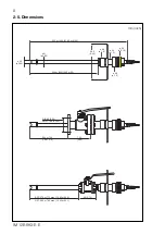
downward (see fig. 2-1). Installation
in a bend of a pipe-line is a good
measurement position.
When inserting the PR20 retracta-
ble fitting in a perpendicular position
to the process flow, the flow veloci-
ty will put a mechanical force on the
probe. Take care that this force is
not too large. It is recommended to
have the PR20 retractable fitting
positioned at a 45° angle into the
process stream.


