IM 12B6K3-E-E
12
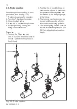
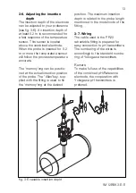
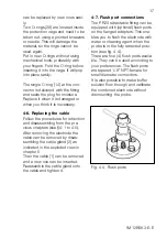
Fig. 3-5. Probe insertion
FIXING SCREW
1
2
3
4
5
2. Pushing the probe into the pro-
cess needs a force to overcome
the pressure of the system and
the friction of the damping rings
in the fitting.
3. The locking mechanism can be
turned until the probe is firmly
fixed at the measuring position.
4. The memory ring can be fixed at
the actual insertion position. See
§3-6 on adjusting the insertion
depth.
3-5. Probe insertion
Insert the probe according to next
procedure (see also fig. 3-5):
1. Position the probe for insertion.
2. Turn the T-bar key clockwise
3. Open the ball-valve.
4. Push the probe into the process.
5. Fix the probe by turning the
fixing screw clockwise.
Remarks:
1. Turning the T-bar key can
ONLY be done when the valve is
closed. Make sure the probe is
firmly fixed.


