


4-7
IM 34M6H55-02E
1st Edition : Apr 1, 2002-00
4.3 Description of Parameters
4.3.1 Entry
parameters
At power up, the content of the flash memory is automatically reloaded to the entry
parameters. Modify the values of the entry parameters as necessary using the Set
Parameter command in an application program. If a parameter value is invalid, the Error
Notification input relay is set, and an entry parameter setting error results. When this
happens, all commands other than the Set Parameter command are disabled. Execute
the Set Parameter command again with valid values. To save the values of the entry
parameters in flash memory, use the Save Parameter command.
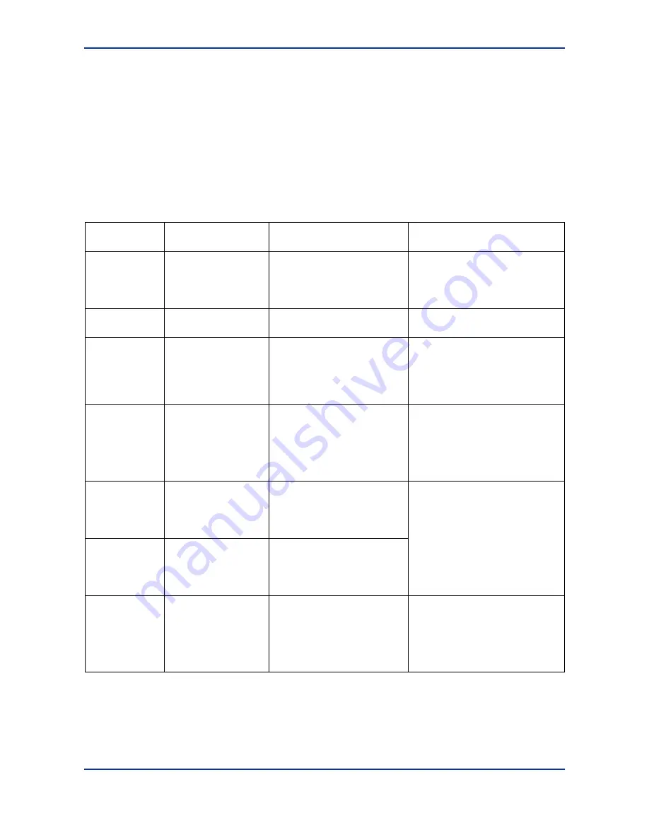
Table 4.5 Entry Parameters
Parameter Type
(Data Position
Number)
Description Data
Range
Remarks
Maximum Speed
Selection (*01)
Sets the maximum
speed of output pulses.
0: 499,750 [pps]
1: 3,998,000 [pps]
[Default: 0]
Set to 0 for pulse motors or 1 for
servomotors. If 1 is selected for pulse
motors, the performance is not
guaranteed. If the maximum speed of
a servomotor used is not more than
499,750 pps, select 0.
Pulse Output
Mode (*02)
Sets the pulse output
mode.
0: Forward/reverse pulse output
1: Direction/travel pulse output
[Default: 0]
Direction of
Rotation (*03)
Sets the relationship
between
positive/negative position
data from the CPU
module and the
forward/reverse pulse
output.
0: Positive value indicates
forward pulse output.
1: Negative value indicates
forward pulse output.
[Default: 0]
Position and negative data here refers
to positioning parameter values set by
a program from the CPU module.
Contact Input
Polarity (*04)
Defines the logic of the
external contact inputs.
Specified for each contact input as
a bit. “0” indicates an “a” contact,
and “1” indicates a “b” contact.
Bit 0: Negative-direction limit
input
Bit 1: Positive-direction limit input
Bit 2: Origin position input
[Default: 0]
An “a” contact input is an input which
is true when a signal input exists, and
a “b” contact input is an input which is
true when no signal input exists. For
example, a “b” contact limit input is
detected when there is no limit signal
and false when there is a limit signal.
Positive-direction
Limit (*05/*06)
Sets the operation limit
position in the positive
direction as the number
of pulses from the origin.
-2147483648 to 2147483647
[pulses]
[Default: 2147483647]
Negative-direction
Limit (*07/*08)
Sets the operation limit
position in the negative
direction as the number
of pulses from the origin.
-2147483648 to (positive-direction
limit value – 1) [pulses]
[Default: -2147483648]
If the origin search is not used, the
current position at power up is used as
the origin. If you start the system after
setting a target position beyond this
range, an error results and the motor
does not start. During an origin search
or jog stepping operation, these limit
values are disregarded (no error
occurs).
Speed Limit
(*09/*10)
Sets the speed setting
range.
1 to 32751616 [(1/65536)
pulse/ms] if maximum speed
selection is 0
1 to 262012928 [(1/65536)
pulse/ms] if maximum speed
selection is 1
[Default:
32751616 (= 499750 pps)]
If a command is given with the target
speed beyond this value, an error
occurs.
The symbol
‘*’
designates the value of (axis number - 1). The values for axis 1 to axis 8 are 0 to 7 respectively.
(Continued on the next page)
Summary of Contents for F3YP14-0N
Page 13: ...Blank Page ...
Page 15: ...Blank Page ...
Page 23: ...Blank Page ...
Page 53: ...Blank Page ...
Page 60: ...7 5 IM 34M6H55 02E 1st Edition Apr 1 2002 00 Figure 7 2 Set Parameter Program ...
Page 65: ...7 10 IM 34M6H55 02E 1st Edition Apr 1 2002 00 Figure 7 6 Jog Stepping Program ...
Page 69: ...7 14 IM 34M6H55 02E 1st Edition Apr 1 2002 00 Figure 7 9 Origin Search Program ...
Page 77: ...7 22 IM 34M6H55 02E 1st Edition Apr 1 2002 00 Figure 7 15 Positioning Operation Program ...
Page 111: ...Blank Page ...
Page 127: ...Blank Page ...


