


IM 01C25T01-01E
3-4
3. OPERATION
3.2 Parameter Usage and Selec-
tion
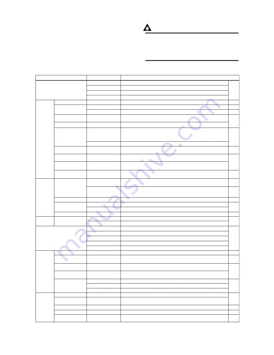
Before setting a parameter, please see the following
table for a summary of how and when each parameter
is used.
IMPORTANT
After setting and sending data with the HART
communicator, wait 30 seconds before turning
off the transmitter. If it is turned off too soon, the
settings will not be stored in the transmitter.
Table 3.2.1 Parameter Usage and Selection
Memory
Transmitter
Display
HART output
Monitoring
Maintenance
Adjustment
T0301.EPS
Item
HART communicator
Description
Page
Tag
Descriptor
Message
Date
Unit
LRV/URV
Apply values
Xfer fnctn
Pres Damp
Low Cut
Low cut mode
Bi-dir mode
Temp Unit
SP Unit
H/L Swap
Disp Pres % fnctn
Disp select
Engr disp range
Burst option
Burst mode
Process Alerts
Poll addr
Polling
Pres and Pres %
AO
Snsr temp
SP and SP %
Engr Disp/exp/Unit
Loop test
Self test and Status
AO Alm typ
Ext SW
Write protect
Enable wrt 10min
New password
Zero trim
Pres and SP sensor trim
D/A trim, Scaled D/A trim
S.C. menu
T.Z. Cmp mode
Tag number, up to 8 characters
Up to 16 characters
Up to 32 characters
xx/yy/zz
Sets the calibration range by the keypad
Range for 4 to 20 mA DC signal is set with actual input applied
Linear or Zero
Used to measure bi-directional flows
Sets a temperature unit displayed on HART communicator
Sets a pressure unit for the static pressure displayed on HART communicator
Used where installation conditions make it imperative to connect high pressure side
impulse line to low pressure side of transmitter
Sets Engr Unit/Modify Engr Unit/Engr LRV/Engr URV/Engr point/Engr exp
Selection of the data to be sent continuously (PV, % range/current, or Process vars/crnt)
ON/OFF switching of burst mode
Used for alarm generation on the integral indicator
Sets the polling address (1 to 15)
ON/OFF switching of multidrop mode
Pressure variable and % output variable
4 to 20 mA output variable
Sensor temperature
Static pressure variable and % static pressure variable
Displays the output of user setting engineering information
Display the status of 4 to 20 mA DC output when a failure occurs
Display/set the external volume protect/permit for LRV (URV) setting
Sets a new password
Sets the current input value to 0 kPa
Adjust the measured differential pressure and static pressure variables
Adjust the output value at the points of 4 mA and 20 mA
Used for compensate the output for the non-linear application
Compensates the zero shift by the ambient temperature effect on the capillary tubes.
Unit
Range
Output mode
Damping time constant
Output signal low cut
mode
Bi-directional flow
measurement mode
Unit for displayed
temperature
Unit for displayed static
pressure
Impulse line connection
orientation
Integral indicator display
mode
Integral indicator scale
Burst mode
Process alarm
Multidrop mode
Test output
Self-diagnostics
Output when CPU error
has occurred
External volume switch
Software write protect
Zeroing
Sensor trim
Analog output trim
Signal characterizer
Capillary fill fluid density
compensation
Sets a pressure unit for the measured pressure
Sets mode for output signal to “linear mode” (proportional to input differential pressure)
or to “Square root mode” (proportional to flow)
Adjust the output response speed for the input pressure of differential pressure
Used mainly to stabilize output near 0 if output signal is the square root mode. Two
modes are available: forcing output to 0% for input below a specific value, or changing
to proportional output for input below a specific value
Sets mode for integral indicator to “linear mode” (proportional to input differential
pressure) or to “Square root mode” (proportional to flow)
Sets the following 5 types of integral indicator scale ranges and unit: input pressure, % of
range, user set scale, input static pressure, % of static pressure range, and alternating
among any four of the above
Used for loop checks. Output can be set freely from –2.5% to 110% in 1% steps
Check using the self-test and status command. If an error is detected, the corresponding
message is displayed
Displays the permit/protect status of setting changes depending on communications
Write protect status is released for 10 minutes when the password is entered
P. 3-6
P. 3-6
P. 3-7
P. 3-8
P. 3-9
P. 3-10
P. 3-11
P. 3-14
P. 3-10
P. 3-11
P. 3-13
P. 3-20
P. 3-25
P. 3-21
P. 3-15
P. 4-1
P. 3-12
P. 3-22
P. 3-23
P. 3-16
P. 3-18
P. 3-24
P. 3-27
—


