background image

12-6

IM AQ1100-01EN

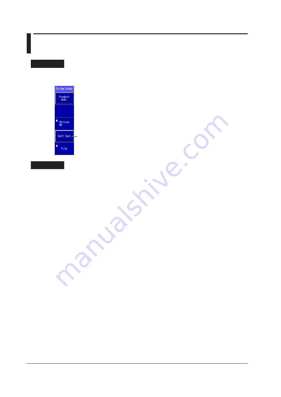
12.4  Performing a Self Test

Procedure

System Setup Menu

Press 

SETUP

 to display the following menu.


Executes a self test 

Explanation

This instrument checks the operation of the:

•  Internal memory.
•  RTC (real time clock) battery.
If the results of the self test are normal, “Test succeeded” appears. If an error occurs, “Test Error 
occurred” appears.

When an Error Occurs during a Self Test

  If an error occurs, contact your nearest YOKOGAWA dealer.

Summary of Contents for AQ1100A

Page 1: ...User s Manual AQ1100A AQ1100B AQ1100D OLTS Multi Field Tester IM AQ1100 01EN 4th Edition...

Page 2: ...AQ1100A AQ1100B and AQ1100D Notes The contents of this manual are subject to change without prior notice as a result of continuing improvements to the instrument s performance and functionality The fi...

Page 3: ...or user s data and precautions that can be taken to prevent such occurrences Note Calls attention to information that is important for proper operation of the instrument Symbols and Conventions Used...

Page 4: ...er Meter PPM suffix code 4 1 Making Preparations for Measurements 4 1 4 2 Setting PON System Optical Power Measurement Conditions and Holding the Display 4 2 4 3 Selecting and Saving Core and Tape Num...

Page 5: ...1 11 2 Configuring Power Save Settings 11 2 11 3 Resetting This Instrument to Its Factory Default Settings 11 3 11 4 Configuring Network Settings Option 11 4 11 5 Restricting Operations 11 6 Chapter 1...

Page 6: ...th subscribers and user networks which enable communication within a corporation or building Optical power meter Loss measurement light source and visible light source Loss measurement that makes use...

Page 7: ...a value from 800 to 1700 nm in 1 nm steps CWDM You can set the wavelength to a value from 1270 to 1610 nm in 20 nm steps along the CWDM wavelength grid 2 You can select the modulation frequency of th...

Page 8: ...M 1550 nm SM 1625 nm AQ1100D GI 850 nm GI 1300 nm SM 1310 nm SM 1550 nm You can produce continuous light or light that has been modulated at the selected frequency modulation mode Visible Light Source...

Page 9: ...reference offset and threshold values can be specified The zero set and measured value display hold operations can be executed You can attach fiber information to the measured values and save them Bec...

Page 10: ...Optical Fiber under Loss Test All fibers other than the optical communication fiber can be tested For each optical fiber under loss test connect one end to the master s optical power measurement port...

Page 11: ...l fiber or line is connected physically IP testing is available on models with the LAN option Pinging To ping an address perform a simple IP test specify the address and configure the Tx frame setting...

Page 12: ...on off Startup menu selection USB function selection storage communication Screen color selection Current date and time configuration see the operation guide IM AQ1100 02EN Power save settings Network...

Page 13: ...he soft key When you press a soft key that corresponds to an item on the menu the selected item is confirmed or the action that corresponds to it is performed B The selected setting switches each time...

Page 14: ...to select the item F The selected setting switches each time you press ENTER G Press ENTER to display a text box Turn the rotary knob or press the up and down arrow keys to increase or decrease a num...

Page 15: ...firm the string that you entered and close the character input dialog box The string be applied to the relevant item You can also confirm the string by moving the cursor to ENT on the displayed keyboa...

Page 16: ...nput history screen 2 Using the rotary knob and ENTER choose the string that you want to enter The string appears in the edit screen Note Entered strings are saved to the input history when you confir...

Page 17: ...soft key SETUP and then the OPM Setup soft key to display the following screen The figure below shows the screen that appears on models with SPM and HPM suffix codes On models with the PPM suffix code...

Page 18: ...th SPM or HPM suffix codes Set the unit dB dBm W Set the reference manually 80 to 40 dBm The Reference box appears if you press the DREF soft key or set the unit to dB see the detailed setup screen in...

Page 19: ...isplay unit to one of the following options dB relative value dBm absolute value W absolute value The following prefixes are attached to W m 10 3 10 6 n 10 9 and p 10 12 The relationship between the a...

Page 20: ...to the light source wavelength and modulation mode settings On After On is selected the power meter settings are synchronized to the light source settings Off The power meter settings are not synchron...

Page 21: ...display items Logging 3 Press the Display soft key to select Logging The following screen appears Date and time See the operation guide IM AQ1100 02EN Cursor Value per division on the vertical axis O...

Page 22: ...ge Displaying and Moving the Cursor 5 Turn the rotary knob to display the cursor Cursor Note The direction that the cursor moves differs depending on the direction that you rotate the rotary knob Cloc...

Page 23: ...destination drive internal memory USB memory Explanation Creating and Saving Logs This instrument is always measuring power when the Power Meter screen is displayed To save the measured values you mus...

Page 24: ...surement range cannot be displayed even if you switch to the other cursor the selected cursor will not be displayed in the center of the screen Auto Zoom The vertical zoom factor is set automatically...

Page 25: ...m factor 5 Cursor position Cursor position Cursor position Press the down arrow key to zoom the graph display vertically Vertical zoom factor 50 Press the left arrow key to zoom the graph display hori...

Page 26: ...e area When Display is set to List Core no When Display is set to Core List You can save up to three sets of data in the save area of the specified core Use the rotary knob and the arrow keys to selec...

Page 27: ...t the list to show to one of the following options The list display format changes depending on the starting core number tape number type and number of fibers or tapes that you set in the detailed set...

Page 28: ...area or delete all the data at once Starting Core Number You can set the starting core number to a value within the following range 1 to 9900 Tape Number Type You can set the tape number type to one...

Page 29: ...eter zero set procedure Procedure Performing Zero Set Press the PON Power Meter soft key SETUP and then the OPM Setup soft key to display the following screen Performs zero set Explanation Perform zer...

Page 30: ...e following screen Holds the measured value display Measured value Bar graph display of the measured value Set the signal direction ONU OLT OLT ONU Lower threshold line Upper threshold line When the S...

Page 31: ...tion the telephone exchange s optical terminal The optical power of the 1310 nm data wavelength signal is measured 2 You can measure the optical power of the downstream signal wavelengths from the OLT...

Page 32: ...its bar graph is green PASS appears in the measured value area When a measured value exceeds the upper threshold or falls below the lower threshold its bar graph is red FAIL appears in the measured va...

Page 33: ...direction is ONU OLT The data set in section 4 2 is displayed Save area Save area When Display is set to List Core no When Display is set to Core List You can save up to three sets of data in the sav...

Page 34: ...set the list to show to one of the following options The list display format changes depending on the starting core number tape number type and number of fibers or tapes that you set in the detailed s...

Page 35: ...ee section 9 2 Deleting Data You can delete the data for individual core numbers in a save area or delete all the data at once Starting Core Number You can set the starting core number to a value with...

Page 36: ...ailable settings vary depending on the model For details see the explanation later in this section Set the wavelength The available settings vary depending on the model For details see the explanation...

Page 37: ...SM 1310 nm SM 1550 nm The light for single mode SM optical fiber is emitted from optical port 2 The light for graded index GI multi mode optical fiber is emitted from optical port 3 Firmly connect th...

Page 38: ...to display the following screen Turning the Light Source On and Off Pressing the VLS Key Press VLS to turn on the visible light A mark appears on this instrument display to indicate that the light is...

Page 39: ...t source ports that do not have optical fiber cables connected to them On models with two or more light source ports visual impairment may occur if light that is mistakenly emitted from the wrong port...

Page 40: ...accordingly Perform optical power adjustment on the light source Optical power adjustment begins when you press the Execute soft key When it ends normally this instrument returns to the previous scree...

Page 41: ...the reference manually 80 to 40 dBm The Reference box appears if you press the DREF soft key or set the unit to dB Sets the reference to the currently displayed measured value Holds the measured value...

Page 42: ...r cable because light is emitted from the light source port Visual impairment may occur if the light enters the eye Close the covers of any light source ports that do not have optical fiber cables con...

Page 43: ...Values For information about the unit reference offset threshold values and the holding of the display of measured values see Explanation in section 3 2 Light Source Measurement Light Wavelength There...

Page 44: ...to the optical power measurement port of the power meter and connect the other end to the light source port of the light source The optical power meter measures the power of the light that passes thr...

Page 45: ...available settings vary depending on the model For details see the explanation later in this section Measured value Bar graph display of the measured value Set the reference manually 80 to 40 dBm The...

Page 46: ...orm loss testing on to this instrument optical power measurement port and connect the other end to the light source port of the same AQ1100A AQ1100B or AQ1100D Executes a loop back loss test The light...

Page 47: ...section 3 2 Light Source Light is emitted at the measurement light wavelength For details see Explanation in section 6 2 Executing a Loop Back Loss Test To perform loop back loss testing configure the...

Page 48: ...Tape no Type is set to Off up to 50 tapes when Tape no Type is set to a b 2 up to 12 tapes when Tape no Type is set to a h 8 Set the wavelength The available settings vary depending on the model For...

Page 49: ...ength from the available settings on this instrument that you are using Model Measurement Light Wavelength AQ1100A SM 1310 nm SM 1550 nm AQ1100B SM 1310 nm SM 1550 nm SM 1625 nm AQ1100D GI 850 nm GI 1...

Page 50: ...asurement port Then transfer the project information 4 Press the Project Transmission START soft key to generate the optical signal used to transmit the project information 3 Press the Receive Project...

Page 51: ...rotary knob and ENTER to select a project information file Restarting an Interrupted Loss Test When the loss test for a shared project is interrupted you can restart it where it left off retaining the...

Page 52: ...have confirmed that the slave is ready to receive the information send it from the master Loading a Project File Load the same project file onto the master and the slave Use a project file that you ha...

Page 53: ...rt enters the eye 3 Press the Loss Test START soft key The optical signal used to transmit the core number is sent to the slave On the menu Loss Test START changes to Loss Test STOP After loss testing...

Page 54: ...key to display the file save screen Follow the procedure in section 9 2 to save the data Explanation Multicore loss testing is performed while information such as project core number loss test result...

Page 55: ...on When adjustment ends normally the AQ1100 returns to the previous screen Cancels optical power adjustment The AQ1100 returns to the previous screen Explanation Optical Power Adjustment Adjust the op...

Page 56: ...ss this soft key to put the screen into the hold state When in the hold state HOLD is displayed at the top of the screen If you press this soft key again the hold state will be cleared File See sectio...

Page 57: ...to execute a ping test Pinging Target Address Specify the address that you want to ping Tx Frame Set the conditions of the frame you will use for pinging Frame Length You can set the length of the fr...

Page 58: ...NG Stop All soft keys other than the PING Stop soft key are unavailable To stop pinging press the PING Stop soft key PING Stop will change to PING Start Ping Test Results The ping test results are lis...

Page 59: ...time regardless of whether this instrument is on or off When the power is on this instrument automatically detects the USB storage medium after it is connected Note Connect USB storage devices to this...

Page 60: ...y knob and ENTER to select the save destination or the file that you want to load Folder path The number of folders and files in the selected folder The file name candidate for the next save operation...

Page 61: ...s PON power meter measurement conditions and optical output conditions CFG System setup data file BMP BMP screen image data file When you select Save the screen image from immediately before you switc...

Page 62: ...n or equal to 200 characters in length If it exceeds 200 characters an error occurs when you perform a file operation such as saving copying renaming or creating a folder Full file path When an operat...

Page 63: ...er Meter soft key SETUP and then the File soft key to display the following screen Use the rotary knob and ENTER to select the files you want to delete or copy Selected files are indicated with this m...

Page 64: ...d Deleting The selected files are deleted Setting the Copy Destination and Copying After selecting the files to copy set the destination folder and copy the files About the File Operation Screen Depen...

Page 65: ...Suffix Codes Press the OPM LS or PON Power Meter soft key SETUP and then the File soft key to display the following screen Set the action Rename Set the file type Set the extension of the file type o...

Page 66: ...character input dialog box that appears Follow the procedure in section 2 2 Use the character input dialog box to enter the extension as well When you press the Commit soft key in the character input...

Page 67: ...want to create the folder in Folder path The number of folders and files in the selected folder Set the destination drive internal memory USB memory Create a folder The character input dialog box appe...

Page 68: ...soft key SETUP and then the File soft key to display the following screen Set the action DeleteFolder Copy Folder Use the rotary knob and ENTER to select the folder you want to delete or copy Folder p...

Page 69: ...the internal memory About the File Operation Screen Depending on the model and the selected feature the operations for opening the file operation screen and the screens that appear vary On models with...

Page 70: ...PPM suffix codes Models with PPM Suffix Codes Press the OPM LS or PON Power Meter soft key SETUP and then the File soft key to display the following screen Set the action Format Formats the internal...

Page 71: ...ker and the print color Starts printing Explanation Action Select Print Print Setup Specify the maker of the printer connected to this instrument and the print color Connect the printer to the USB Typ...

Page 72: ...Year month day hour minute second year month day hour minute year short form month day hour minute month day hour minute hour minute Set what to sort by Date File Name Set the sort order A Z Z A Turn...

Page 73: ...options that appear vary depending on the product s language specification Turning the Beep On and Off You can make this instrument beep whenever an operation error occurs or an error message is displ...

Page 74: ...off automatically after 30 minutes LCD Brightness You can set the LCD brightness Bright The screen is bright Choose this setting when you are in a bright area Because this setting uses a great deal of...

Page 75: ...ettings All the settings are reset to their factory defaults but the internal memory and the day and time settings excluding the type are not initialized Initializing All Settings All the settings are...

Page 76: ...a that is stored on this instrument internal memory For details about the network that you intend to connect this instrument to contact your network administrator Enabling or Disabling the Network Set...

Page 77: ...ibed in the previous section Check the information when you access this instrument from a PC IP Address You can set the IP address assigned to this instrument The IP address is an ID that is assigned...

Page 78: ...e following screen Displays the Change Administrator PIN screen Displays the Operation Lock Setup screen see step 4 Changing the Administrator PIN 3 Using the rotary knob and ENTER select Change Admin...

Page 79: ...or details see IM AQ1100 01EN which is contained in the included CD Explanation You can restrict the following operations by requiring a PIN password to be entered before they can be performed Operati...

Page 80: ...he settings 11 2 The screen is dark The screen is dark when the LCD Brightness setting is set to Power save Check the settings 11 2 The LCD may be worn out Servicing is required 12 11 When the tempera...

Page 81: ...rdware failed and needs to be repaired Please contact Yokogawa s representatives 512 ZERO SET ERROR 513 ZERO SET ERROR 514 Exceeding limit It may cause damage of the instrument Please disconnect the p...

Page 82: ...ollowing Media is correctly installed Media is formatted Media is not read only 645 The path name is too long 646 USB memory can not be recognized 647 Can not make file or folder in this folder 690 Ca...

Page 83: ...repaired Please contact Yokogawa s representatives 906 Battery is low The instrument will be powered off in 10 sec 909 The temperature inside the instrument is too high The instrument may be damaged...

Page 84: ...then the Product Info soft key to display the following screen Saves a screen image Explanation The following information about this instrument is displayed Model Name Serial Number Suffix Code Mac A...

Page 85: ...es a self test Explanation This instrument checks the operation of the Internal memory RTC real time clock battery If the results of the self test are normal Test succeeded appears If an error occurs...

Page 86: ...re update file internal memory USB memory Explanation To update the firmware select a firmware update file YMC extension You can change file names except for the extension as necessary For instruction...

Page 87: ...This instrument may not operate properly if its connectors are loose Make sure that There is no external damage or deformation on the outside of this instrument There are no switches connectors or oth...

Page 88: ...hem clean them thoroughly with clean water and then see a doctor immediately Do not use or charge battery packs with this instrument that are not made by YOKOGAWA When you attach the battery pack to t...

Page 89: ...n your area When disposing of the batteries in the EU follow the Waste Electrical and Electronic Equipment WEEE Directive Contact your nearest YOKOGAWA dealer under the following circumstances When th...

Page 90: ...ry case Battery cover Hooks Hook holes Electrodes Charging a Battery Pack When the battery is low a warning message will appear When this happens charge the battery 1 Connect the power cord to the AC...

Page 91: ...adapter while the power is on you may accidentally get light in your eyes damage them and impair your vision Removal 1 Make sure that this instrument power is off 2 Open the optical port cover 3 Pull...

Page 92: ...r directly into the rear shell 4 Pull the optical adapter lock lever down and outwards to lock it If the adapter is screwed in turn the knob to the right to tighten it Good example Bad example Note In...

Page 93: ...t source port If you clean the optical components while the power is on you may accidentally get light in your eyes damage them and impair your vision 1 Make sure that this instrument power is off 2 O...

Page 94: ...fully charged after it has just been charged or when it has no power left when the instrument will not turn on Storing the battery pack under these conditions will degrade its performance and reduce...

Page 95: ...ed Consumables We recommend that you replace the following parts at the intervals listed below Part Name Recommended Replacement Interval Notes Backup battery lithium battery 5 years Send to factory t...

Page 96: ...4 5 6 7 8 9 10 11 12 Index App 12 12 Calibration Periodic calibration is an effective means of keeping the instrument performing correctly for a long time and of detecting malfunctions at an early st...

Page 97: ...1 2 3 4 5 6 7 8 9 10 11 App Index Appendix 1 Data File Formats CSV File Formats The following examples show the saved data being displayed in a spreadsheet program Logged Results Measured Data from th...

Page 98: ...App 2 IM AQ1100 01EN Loss Test Results Project Information Appendix 1 Data File Formats...

Page 99: ...urement light 1 3 measurement light wavelength 5 2 mechanical inspection 12 8 model name 12 5 modulation mode light source 1 3 5 2 modulation mode optical power meter 1 2 3 3 multicore loss testing 1...

Page 100: ...e 1 2 3 3 rotary knob and ENTER 2 2 rotary knob operations 2 2 S Page saving 10 3 screen color 11 1 screen save 11 2 self test 12 6 serial number 12 5 shipping 12 15 simple wavelength mode 3 3 skippin...

Reviews: