YMGI WMMS-09EW-V2B(59)2 Installer'S Instruction & User'S Manual Download Page 17

UNIT MAINTENANCE & 

SER

VICE GUIDE

P32 OF 46

YMGI, Engineered Comfort Products for A Sustainable and Efficient Green World !

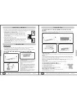
Hearing sound of "water flow" inside unit.

Normally this is due to refrigerant flowing through coils.

Mist is blown out of unit.

Normally it happens during cooling start period, when indoor 
air is hot and humid.

Hearing creaking noise during unit starting or shutting off.

Normally this is caused by the expansion or contraction at 
components due to the temperature changes.

The unit doesn't operate at all.

1) Is power shut off or lost?

2) Is TIMER set up?

3) Is circuit breaker not engaged, or even trips?

4) Is fuse not connected, or even blown?

5) Is voltage too high or low?

6) Is the flow control or other switches breaking the circuit?

7) Is unit under 3-minute restarting protection period?

8) Is the remote control our of battery power? 

Phenomenon

Normal or Abnormal

Unit doesn't respond to remote control.

1) Is the remote control our of battery power?

2) Is remote control pointing to sunshine or lighting?

3) Is remote control signal blocked?

4) Is remote control too far away from indoor unit?

5) Is the fuse on indoor unit blown?

6) Is the indoor unit powered on?

7) Is the indoor unit transformer good?

8) Is the indoor unit control board good?

Cooling (heating) is not powerful.

1) Is the set temperature too high or too low?

2) Is filter dirty?

3) Is air vent blocked?

4) Is unit undersized?

5) Is window or door closed?

6) Is unit refrigerant at lower level?

7) Is outdoor too hot or cold?

8) Is fan speed set at low?

CHECKING UNITS PRIOR TO CONTACTING YOUR TECHNICIAN

UNIT MAINTENANCE & 

SER

VICE GUIDE

P31 OF 46

YMGI, Engineered Comfort Products for A Sustainable and Efficient Green World !

Do not repair the air conditioner at your discretion. Incorrect repair may cause electric shock or fire, so please 
contact authorized service center for professional repair.

Following checks prior to contact may save your time and costs.

Phenomenon

Normal or Abnormal

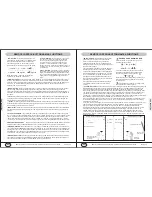
The unit doesn't deliver cooling or heating, immediately after the 
unit is restarted (remote control or power resuming).

If unit is powered off, and then restored, it will not run the 
compressor until 3 minutes later. This is normal 3-minutes 
restarting protection against high internal refrigerant pressure. 

The unit emits a smell.

For new unit, some of the smell is normal.
For any bad or abnormal smell, need to shut off the unit and 
check around. May need to call your technician.

CHECKING UNITS PRIOR TO CONTACTING YOUR TECHNICIAN

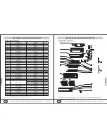
System abnormal (anti-high temp, power off, cooling overload)

Compressor overload protection

H3

Blink 3 times

Module protection

High-pressure protection

Anti-freeze protection power-off

Discharge temperature protection

Low voltage over-current protection

Mode clash

Communication malfunction

Indoor ambient temp sensor open, short circuit

Defrost or heating oil return

Protection and Error Code Names

Dual-8 Display Running Lamp Heating Lamp Cooling Lamp

H4

H5

E1

E2

Blink 4 times

Blink 5 times

Blink once

Blink twice

E4

E5

E7

E6

H1

Blink 4 times

Blink 5 times

Blink 7 times

Blink 6 times

Blink once

F1

F2

F3

F4

F5

H7

HC

HE

Blink once

Blink twice

Blink 3 times

Blink 4 times

Blink 5 times

Blink 7 times

Blink 6 times

Blink 14 times

F6

F8

Blink 6 times

Blink 8 times

PROTECTION AND ERROR CODES

Indoor unit temp sensor open, short circuit

Outdoor ambient temp sensor open, short circuit

Outdoor unit temp sensor open

Outdoor unit discharge temp sensor open

Fail to start up

PFC malfunction

Compressor demagnification protection

Cooling overload down frequency

Unit overflow down frequency

F9

E0

H0

E9

F7

Blink 9 times

Blink 10 times

Blink 10 times

Blink 9 times

Blink 7 times

Compressor discharge down frequency

Unit AC voltage decreasing down frequency

Heat anti high temp down frequency

Anti cool air protection

Cooling oil return

Summary of Contents for WMMS-09EW-V2B(59)2

Page 1: ...r Local Codes and related manuals from YMGI Otherwise damage to equipment or property even injury to people may occur Installer Currently licensed HVAC technician only Read manual before installation...

Page 2: ...d for an extended period of time The information we provide in our manuals is for the sole purpose of reminding you and your installer It is our ultimate goal to help insure that your YMGI units are i...

Page 3: ...e humidity ranges installation operation maintenance service warranty parts and so on 4 Properly select correct most suitable YMGI product models of units and accessories for your HVAC applications jo...

Page 4: ...he installation 5 Supply electrical power V Ph Hz measured at wiring terminal block of Indoor unit outdoor unit 7 Wire gauge length and terminal colors between circuit breaker disconnect switch to out...

Page 5: ...rvice contractor otherwise 3 The distributor where the unit is purchased from otherwise 4 YMGI Technical Support Tel 866 833 3138 703 Email techsp ymgigroup com Regular equipment maintenance or field...

Page 6: ...0 0 2 1 Cross Flow 1 3 6 x25 4 MP24AA 2 2 4 NA Blue Yes 1 4 3 8 0 67 NA Yes Standard Washable 2 Yes Yes Yes Yes 32 7 x 11 2 x 7 9 35 7 x 15 2 x 10 7 24 3 30 8 240 480 540 208 230 1 60 187 253V 12000 9...

Page 7: ...PE OUT TEM SENSOR ROOM TEM SENSOR FAN MOTOR M1 RT4 RT3 RT2 RT1 4 3 2 TUBE 1 TUBE TUBE 0 ROOM PG PGF CAP JUMP AP2 DISP1 DISP2 SWING UD TR OUT1 TR IN M2 N1 COMU AC L BU BK BN XT N 1 2 3 YEGN E INDOOR UN...

Page 8: ...Tool Set Not Shown Hex Head Key Set Torch for AC Application Not Shown Heat Absorbtion Flux Nitrogen Not Shown Soap Bubble Not Shown Vacuum Pump Helium Leakage Check Not Shown Manifold Wire Cutter Wir...

Page 9: ...door unit B Indoor unit C OVER 20 OVER 10 OVER 10 OVER 8 OVER 10 OVER 2 OVER 4 OVER 4 OVER 80 INSTALLER S INSTRUCTION P16 OF 46 YMGI Engineered Comfort Products for A Sustainable and Efficient Green W...

Page 10: ...uctions of all units thoroughly Ask rep distributor us anything you are not sure about Get your tools and parts ready for installation CAUTION SUGGESTIONS TO FOLLOW PRIOR TO INSTALLATION PIPING AND WI...

Page 11: ...plate holes with those holes drilled on the wall and put anchors or screws into the holes to secure mounting plate Steps To Mount Plate a b c Drill mounting holes to make sure at least either one of t...

Page 12: ...For distance other than 25 between indoor and horizontal venting condensing units refer to the following table for copper sizes Make sure the pipe section where is to be cut is straight and smooth App...

Page 13: ...t mode you would like the unit to run in When the remote is first turned on the mode displayed will be the AUTO mode The temperature cannot be adjusted in this mode and will not display on the indoor...

Page 14: ...emote press the TIMER ON button once more and the word ON will stop blinking and stay on the remote The time you would like the unit to turn on is now set TIMER OFF BUTTON This allows you to set the t...

Page 15: ...he same time COOLING Running symbol and cooling symbol are lit HEATING Running lamp and heating symbol are lit DRY Running lamp and dry lamp are lit FAN Running lamp and fan lamp are lit AUTO Auto lam...

Page 16: ...or discoloration to Install front panel Place two supporters of the front panel into the slots along the direction of arrows to cover and clasp the front panel As show in right figure If at any time t...

Page 17: ...orized service center for professional repair Following checks prior to contact may save your time and costs Phenomenon Normal or Abnormal The unit doesn t deliver cooling or heating immediately after...

Page 18: ...leaking 3 Is condensate drain hose clogged or restricted 4 Is condensate drain hose insulated 5 Is the 3 hole at exterior wall staffed or sealed Noise is heard at indoor unit 1 Is the fan motor or co...

Page 19: ...32 Transformer 48X26P 1 33 Wire clamp 1 34 Rear clamp 1 35 Connecting cable 1 36 swing louver clamp 1 37 swing louver 1 38 swing louver up 1 39 swing louver down No Description Tube sensor 20K Part C...

Page 20: ...1 Front panel 200022921 1 Guide louver 261120432 1 Guide louver 261120422 1 Motor MP28EC 15212002 1 Right motor clamp 26112429 1 Bearing holder 26152423 1 Motor FN20M PG 150120873 1 Electric box cove...

Page 21: ...experience to correct the problem more efficiently A technician s may be unwilling to repair an issue on a unit that they did not install If you do find a technician willing to perform the service the...

Page 22: ...ereafter in this and other documents that we publish 2 You will follow what is written hereafter in this and other documents that we publish 3 You will be bound by and completely follow all policies g...

Page 23: ...s available based on the actual need at YMGI s determination This option shall be the last resort due to refrigerant and wiring considerations All unit removal re installation and shipping cost are th...

Page 24: ...Read and follow all policies set forth from the distributor from which you purchased your unit Upon purchase and installation of the unit s you agree to be bounded by all policies published by both di...

Reviews: