


INST
ALLER'S
INSTRUCTION
P21 OF 46
YMGI, Engineered Comfort Products for A Sustainable and Efficient Green World !
*
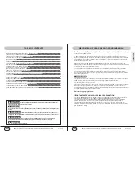
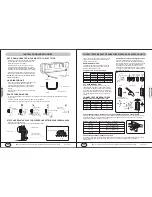
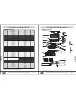
To drain the condensate easily, the drain hose should be inclined downward (pitched towards drain direction
1/4" per foot).
* Figures below from the 2nd to 5th show some incorrect
.
practices
* Drain hose may be extended using the hose coming with the installation list.
STUFF AND SEAL THE HOLE FOR COPPER LINE SET/WIRE CABLE/DRAIN HOSE
* Use putty to seal the wall hole.
* Use clamp (pipe fastener) to secure the pipe at specified position.
SHAPE THE DRAIN HOSE
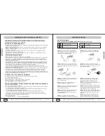
REFIT DRAIN HOSE FROM THE RIGHT TO THE LEFT SIDE
* If drain hose needs to be refitted from the original
position (right side) to left side of the indoor unit,
careful handing is very necessary.
* Refitting method: remove the drain hose from
original position, without breaking hose. Unplug
the plug at the left side. Apply water-resistant glue
to fit the drain hose and the fitting before securing it.
* Apply water-resistant glue onto the plug and fit it
back into the condensate connection at right side.
NOTES: May use some sort of clamp to double
secure connections.
Condensate connection
at left side
Drain hose
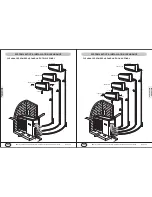
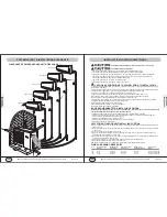
HANG INDOOR UNIT
* Run copper set/wire cables/drain hose through the
wall hole and hang the indoor unit onto the
mounting plate (place the hook on the mounting
plate into the hanging rib at rear side of plastic
casing).
* Snap the plastic casing bottom into the mounting
plate, gently .
Sealed with putty
Secure the piping/
wiring set with clamp
Trim the extra portion
2 in or less
from floor
dip hose in water
water
leak
standing
water
air
water
leak
rise up
water
leak
decline
downward
Indoor unit
Bottom
the rib of indoor unit
the mounting plate
Indoor unit
Screw
Clamp
INSTALLATION-INDOOR UNITS
INST
ALLER'S
INSTRUCTION
P22 OF 46
YMGI, Engineered Comfort Products for A Sustainable and Efficient Green World !
CONNECT REFRIGERANT PIPES BETWEEN INDOOR AND OUTDOOR UNITS
Firstly, connect copper tubes at indoor unit. Bend
pipes by tools but not by hands. Extra length is
needed for future service.
REFRIGERANT PIPES:
For distance other than 25' between indoor and
horizontal venting condensing units, refer to the
following table for copper sizes.
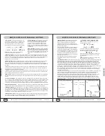
Make sure the pipe section where is to be cut is
straight and smooth. Apply cutting blade straightly
perpendicular to the pipe surface. Don't cut too fast
or too hard. Turn and tighten the tube cutter slowly.
Remove residual left and de-bur at the cutting edge.
The cutting edge should be clear and clean and
smooth.
Running Interconnection Refrigerant Lines:
Use clean refrigeration grade of copper pipe only.
Keep the copper lines from kinking and transmitting
noise to walls, cabinets, etc. Pipe length not to exceed
150', elevation not to exceed 35. Insulate both the
liquid and gas copper lines with at least 3/8" thick
insulation tubes. Band and tape and secure refrigerant
lines. Support copper lines at proper distance apart to
keep tubes from sagging.
CUT REFRIGERANT PIPE:
Connect Copper Pipes-Flare/nut Connection at Both Indoor and Outdoor Units
Proper torque shall be applied to make good connection at female nut, flare and male nut, as recommended in
the following table. Too much torque may damage and break flare/nut seal. Too less torque may not ensure
a good seal. ALWAYS use a pair of wrenches.
Flare Nut
1/4-3/8"
1/4-1/2"
1/2-3/4"
7/8-1 1/8"
Tightening Torque
25 Ft. LBs (350 Kgf.cm)
40 Ft. LBs (560 Kgf.cm)
60 Ft. LBs (840 Kgf.cm)
110Ft. LBs (1540 Kgf.cm)
Refrigerant Pipe Flare/Nut Connection Tightening Torque
Refrigerant Pipe Length and Height
CONNECT REFRIGERANT PIPES
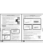
In this case, put wet rag to protect valves or other components from being overheated. When using flux, rub the
tube surface using steel wool to shine and clean to dry as so to keep the system from any possible
contamination.
Connect Copper Pipes-Sweat Connection
Refrigerant Valve and Pipe Size/Length
K
Btu/h
09
12
18
Valve Size
Liq, Gas
1/4", 3/8"
1/4", 3/8"
1/4", 1/2"
15-30ft
1/4 , 3/8
"
"
1/4 , 3/8
"
"
1/4 , 1/2
"
"
31-60ft
1/4 , 3/8
"
"
1/4 , 3/8
"
"
1/4 , 1/2
"
"
Line Sizes at Different Length
1,000 Btu/h
09
12
18
24
Height (Ft.)
3.82
3.6
3.8
5.0
Length (Ft.)
23
24.3
31.4
50
Cut too
hard
Cut too
hard/fast
Angle
Inclined
Twist to cut pipe
O
90
Bad cut
De-burring tool
Fixed
Need to properly
select dimensions A per D
Pipe flare
expander
Canter line
Canter line
Expander
Head
Copper line
24
1/4", 5/8"
1/4", 5/8"
3/8 , 5/8
"
"


