


UNIT OPERA
TION
P27 OF 46
YMGI, Engineered Comfort Products for A Sustainable and Efficient Green World !
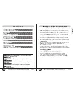
REMOTE CONTROL-BUTTON NAME & FUNCTIONS
INTRODUCTION FOR SPECIAL FUNCTION
This function indicates that there is moisture on the evaporator of the indoor unit will be blowed after the unit has
stopped to avoid mold.
1) Having set blow function on: After turning off the unit by pressing ON/OFF button indoor fan will continue
running for about 10 min. at low speed. In this period, press blow button to stop indoor fan directly.
2) Having set blow function off: After turning off the unit by pressing ON/OFF button, the complete unit will be off
directly.
About blow function
About AUTO RUN
When AUTO RUN mode is selected, the setting temperature will not be displayed on the LCD, the unit will be in
accordance with the room temp. automatically to select the suitable running method and to make ambient
comfortable.
* About turbo function
At the start of this function, the unit will blow at super high speed to cool or heat quickly so that the room temp.
approaches the preset temp. as soon as possible.
1) Press swing up and down button continuously more than 2s,the main unit will swing back and forth from up
to down, and then loosen the button, the unit will stop swinging and present position of guide louver will be
kept immediately.
2) Under swing up and down mode, when the status is switched from off to , if press this button again 2s later,
status will switch to off status directly; if press this button again within 2s,the change of swing status will
also depend on the circulation sequence stated above.
* About swing up and down
Press +and - buttons simultaneously to lock or unlock the keyboard. If the remote controller is locked, the icon
will be displayed on it, in which case, press any button, the mark will flicker for three times. If the keyboard
is unlocked, the mark will disappear.
* About lock
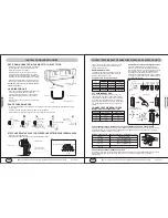
SYMBOL DISPLAY
When power is first applied to the unit but the power has not been turned on by the remote control, then the red
power light only is displayed. When the unit has been powered on by the remote control then the running LED is
lit and the current running mode symbol is displayed at the same time.
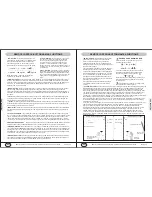
COOLING:
Running symbol and cooling symbol are lit.
HEATING:
Running lamp and heating symbol are lit.
DRY:
Running lamp and dry lamp are lit
FAN:
Running lamp and fan lamp are lit.
AUTO:
Auto lamp, running lamp and actual running mode are lit.
ALPHA NUMERIC DISPLAY
O
O
*
The setting temperature range for the unit is 61 to 86 F.
O
O
* Under AUTO mode unit will display 77 F for cooling and 68 F for heating modes.
UNIT OPERA
TION
P28 OF 46
YMGI, Engineered Comfort Products for A Sustainable and Efficient Green World !
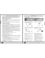
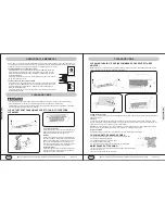
CHANGING BATTERIES AND NOTICES
1) Press slightly along the arrowhead direction to push the back cover open on remote control.
2) Take out the old batteries. (As show in figure)
3) Insert two new AAA1.5V dry batteries, and pay attention to the polarity. (As show in figure)
4) Attach the back cover of wireless remote control. (As show in figure)
NOTE:
When changing the batteries, do not use the old or
different batteries, otherwise, it can cause the
malfunction of the wireless remote control.
The operation should be in its receiving range.
It should be placed at where is 1m away from the TV set or stereo sound sets.
If the wireless remote control can not operate normally, please take them out, after 30s later and reinsert, if they
cannot normally run, please change them.
If the wireless remote control will not be used for and
extended period of time, it is recommended to leave
the batteries out as this could cause leakage from the
batteries. This will damage the remote control.
Sketch map for
changing batteries
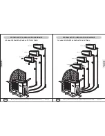
OPERATION OF REMOTE CONTROL
①
②
③
④
①
②
③
④
⑤
UNIT DEFROSTING CYCLE
While the unit is running in HEAT mode during colder weather, frost can build up on the outdoor coil. This is
common on all heat pump units made by all manufactures. If the unit is running and the automatic defrost mode
is enacted the indoor unit will stop running and display an H1 code. Once the defrost cycle is finished and the
outdoor coil is defrosted the indoor unit will start to run again in the mode that it was last set up for.
ON DEMAND DEFROSTING
If at any time you would like the send the unit into the defrost cycle, you can choose to by turning the remote
controller off and pressing the BLOW and the MODE buttons simultaneously. You will see the symbol of HI
appear on the remote. To stop the defrost cycle simply press the BLOW and MODE buttons again and the H1
will disappear from the remote screen.


