


3.4 I/O Signal Allocations
3-27
3
Wi
ring and
C
onne
ctio
n
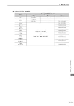
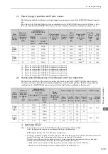
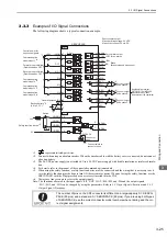
∗1.
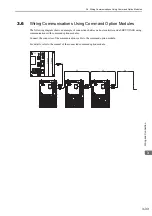
For details, refer to the manual of the connected command option module.
∗2.
These pins cannot be used.
Note: The factory settings of the parameters in a large-capacity
Σ
-V SERVOPACK are not all the same as those for a stan-
dard
Σ
-V SERVOPACK. Make sure that you consider any differences in the factory settings if you copy the param-
eters from a standard
Σ
-V SERVOPACK to a large-capacity
Σ
-V SERVOPACK.
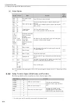
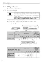
3.4.2
Output Signal Allocations
Output signals are allocated as shown in the following table.
Refer to the
Interpreting the Output Signal Allocation Tables
and change the allocations accordingly.
<Interpreting the Output Signal Allocation Tables>
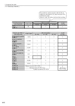
Forward External
Torque Limit
Pn50B.2
L
/P-CL
0
1
2
3
4
5
6
7
8
H
P-CL
9
A
B
C
D
E
F
Reserve External
Torque Limit
Pn50B.3
L
/N-CL
0
1
2
3
4
5
6
7
8
H
N-CL
9
A
B
C
D
E
F
Command Option
Module Input 1
*1
Pn511.0
L
/SI1
0
1
2
3
4
5
6
7
8
H
SI1
9
A
B
C
D
E
F
Command Option
Module Input 4
*1
Pn511.1
L
/SI4
*2
*2
*2
*2
4
5
6
7
8
H
SI4
*2
*2
*2
*2
D
E
F
Command Option
Module Input 5
*1
Pn511.2
L
/SI5
*2
*2
*2
*2
4
5
6
7
8
H
SI5
*2
*2
*2
*2
D
E
F
Command Option
Module Input 6
*1
Pn511.3
L
/SI6
*2
*2
*2
*2
4
5
6
7
8
H
SI6
*2
*2
*2
*2
D
E
F
DB Answer
Pn515.2
L
/DBANS
0
1
2
3
4
5
6
7
8
H
DBANS
9
A
B
C
D
E
F
(cont’d)
Input Signal Names
and Parameters
Validity
Level
Input
Signal
CN1 Pin Numbers
Connection Not
Required
(SERVOPACK
judges the
connection)
40
41
42
43
44
45
46
Always
ON
Always
OFF
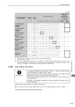
• The signals not detected are considered as
"
Invalid.
"
For example, Positioning Com-
pletion (/COIN) signal in speed control is
"
Invalid.
"
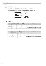
• Inverting the polarity of the brake signal (/BK), i.e. positive logic, will prevent the hold-
ing brake from working in case of its signal line disconnection.
If this setting is absolutely necessary, check the operation and confirm that there are
no safety problems.
• When two or more signals are allocated to the same output circuit, a signal is output
with OR logic circuit.