YASKAWA MP Manual Download Page 58

MP/INVERTER/SERVO Ethernet Driver  

GP-Pro EX Device/PLC Connection Manual

58

8

Write the settings to the Sub CPU.

-V Series Setting

Set up communication settings with rotary switches (S1 and S2).

For details on communication settings, please refer to the manual of the External Device.

Notes

Check with a network administrator about IP address. Do not set the duplicate IP address.

• To write the settings, select the [Save to flash after transferring to the controller] check 

box.

 If the data is transferred without selecting the check box, the transferred data is 
deleted when restarting the External Device.
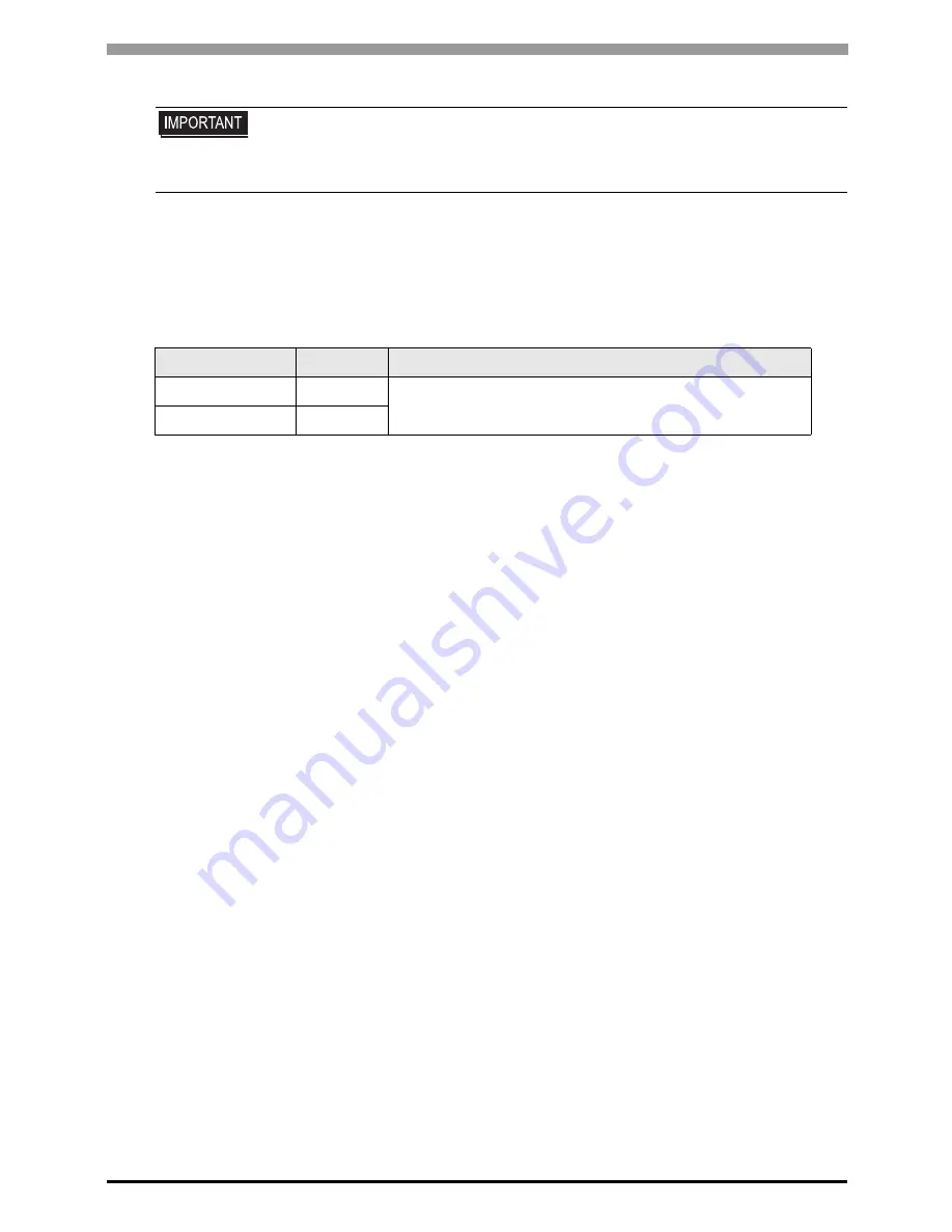
Rotary Switch

Settings

Setup Description

S1 (x16)

0

Station address

S2 (x1)

3

Summary of Contents for MP

Page 1: ...poration MP INVERTER SERVO Ethernet Driver 1 System Configuration 3 2 External Device Selection 12 3 Communication Settings 13 4 Setup Items 80 5 Supported Devices 86 6 Device Code and Address Code 10...

Page 2: ...and SIO that you can connect 1 System Configuration page 3 2 External Device Selection Select a model series of the External Device and its connection method 2 External Device Selection page 12 3 Com...

Page 3: ...t UDP 3 3 Setting Example 3 page 19 Ethernet port on 218IF 02 Ethernet UDP 3 4 Setting Example 4 page 22 MP2400 Ethernet Connector on CPU unit Ethernet UDP 3 2 Setting Example 2 page 16 MPU 01 1 1 The...

Page 4: ...ro EX page 80 MPU 01 1 1 Connection 1 n Connection 1 When 33 or more External Devices are connected it is necessary to check Increase allowable number of Devices PLCs 4 1 Setup Items in GP Pro EX page...

Page 5: ...essary to check Increase allowable number of Devices PLCs 4 1 Setup Items in GP Pro EX page 80 A Sub CPU can be communicated via a Main CPU or in direct connection When connecting to the Sub CPU via t...

Page 6: ...ces PLCs 4 1 Setup Items in GP Pro EX page 80 Series CPU 1 1 The symbol in the inverter model name represents the maximum applicable motor capacity and other specifications Link I F Communication Sett...

Page 7: ...LINK Communications Connectors on MPU 01 Ethernet UDP and MECHATROLINK III 3 14 Setting Example 14 page 48 MECHATROLINK Communications Connectors on Sub CPU Ethernet UDP and MECHATROLINK III 3 17 Sett...

Page 8: ...PLC Connection Manual 8 Connection Configuration 1 1 Connection 1 n Connection 1 When 33 or more External Devices are connected it is necessary to check Increase allowable number of Devices PLCs 4 1 S...

Page 9: ...PLC Connection Manual 9 Connection via MPU 01 1 1 Connection 1 n Connection 1 When 33 or more External Devices are connected it is necessary to check Increase allowable number of Devices PLCs 4 1 Set...

Page 10: ...PLC Connection Manual 10 Connection via Sub CPU 1 1 Connection 1 n Connection 1 When 33 or more External Devices are connected it is necessary to check Increase allowable number of Devices PLCs 4 1 Se...

Page 11: ...onnection Manual 11 Connection via Sub CPU and MPU 01 1 1 Connection 1 n Connection 1 When 33 or more External Devices are connected it is necessary to check Increase allowable number of Devices PLCs...

Page 12: ...the External Device which can be connected in MP INVERTER SERVO Ethernet in system configuration 1 System Configuration page 3 Port Select the Display port to be connected to the External Device Use...

Page 13: ...Device Setting To display the Individual Device Settings dialog box from Device Specific Settings in the Device PLC window select the External Device and click Settings To connect multiple External D...

Page 14: ...its setting information is displayed in the Engineering Manager s Module details 5 In the Module details double click the No field s numeric portion Double click the number associated with the slot nu...

Page 15: ...click No 1 and set up serial communication Serial communication is used to transfer communication settings to the PLC 7 Save the settings and exit Engineering Manager 8 After turning ON the communicat...

Page 16: ...ox from Device Specific Settings in the Device PLC window select the External Device and click Settings To connect multiple External Devices from Device Specific Settings in the Device PLC window clic...

Page 17: ...e communication module When you select the communication module its setting information is displayed in the Engineering Manager s Module details 5 In the Module details double click the No field s num...

Page 18: ...ed with the slot number connected to the Ethernet unit 6 Save the settings and exit Engineering Manager 7 After turning ON the communication module s INIT DIP Switch turn ON the power supply 8 Write t...

Page 19: ...ox from Device Specific Settings in the Device PLC window select the External Device and click Settings To connect multiple External Devices from Device Specific Settings in the Device PLC window clic...

Page 20: ...e communication module When you select the communication module its setting information is displayed in the Engineering Manager s Module details 5 In the Module details double click the No field s num...

Page 21: ...ed with the slot number connected to the Ethernet unit 6 Save the settings and exit Engineering Manager 7 After turning ON the communication module s INIT DIP Switch turn ON the power supply 8 Write t...

Page 22: ...ox from Device Specific Settings in the Device PLC window select the External Device and click Settings To connect multiple External Devices from Device Specific Settings in the Device PLC window clic...

Page 23: ...e communication module When you select the communication module its setting information is displayed in the Engineering Manager s Module details 5 In the Module details double click the No field s num...

Page 24: ...ated with the slot number connected to the Ethernet unit 6 Save the settings and exit Engineering Manager 7 After turning ON the communication module s INIT DIP Switch turn ON the power supply 8 Write...

Page 25: ...Device PLC window select the External Device and click Settings To connect multiple External Devices from Device Specific Settings in the Device PLC window click Add Device to add another External De...

Page 26: ...le details 6 In the module Details s Circuit Number field enter 01 Set up the same value as the Display s circuit number 7 In Details double click MECHATROLINK 8 Click the Link Assignments tab and the...

Page 27: ...station address in combination with the DIP Switch SW2 number 3 Notes Check with a network administrator about IP address Do not set the duplicate IP address DIP Switch Settings Setup Description 1 O...

Page 28: ...Device PLC window select the External Device and click Settings To connect multiple External Devices from Device Specific Settings in the Device PLC window click Add Device to add another External De...

Page 29: ...le details 6 In the module Details s Circuit Number field enter 01 Set up the same value as the Display s circuit number 7 In Details double click MECHATROLINK 8 Click the Link Assignments tab and the...

Page 30: ...station address in combination with the DIP Switch SW2 number 3 Notes Check with a network administrator about IP address Do not set the duplicate IP address DIP Switch Settings Setup Description 1 O...

Page 31: ...Device PLC window select the External Device and click Settings To connect multiple External Devices from Device Specific Settings in the Device PLC window click Add Device to add another External De...

Page 32: ...gineering Manger s Module details 6 In the module Details s Circuit Number field enter 01 Set up the same value as the Display s circuit number 7 In Details double click MECHATROLINK 8 Click the Link...

Page 33: ...nication settings with rotary switches S1 and S2 For details on communication settings please refer to the manual of the External Device Notes Check with a network administrator about IP address Do no...

Page 34: ...Device PLC window select the External Device and click Settings To connect multiple External Devices from Device Specific Settings in the Device PLC window click Add Device to add another External De...

Page 35: ...gineering Manger s Module details 6 In the module Details s Circuit Number field enter 01 Set up the same value as the Display s circuit number 7 In Details double click MECHATROLINK 8 Click the Link...

Page 36: ...nication settings with rotary switches S1 and S2 For details on communication settings please refer to the manual of the External Device Notes Check with a network administrator about IP address Do no...

Page 37: ...dialog box from Device Specific Settings in the Device PLC window select the External Device and click Settings To connect multiple External Devices from Device Specific Settings in the Device PLC win...

Page 38: ...e 2 Make a project file 3 Click Module Configuration to start MC Configurator 4 Double click 218IFD on the CPU you want to use 5 Click the Transmission Parameters tab 6 In the Transmission Parameters...

Page 39: ...gs dialog box from Device Specific Settings in the Device PLC window select the External Device and click Settings To connect multiple External Devices from Device Specific Settings in the Device PLC...

Page 40: ...ting Mode screen Press ENTER to change to Set Up Mode 2 Press UP to display setup items Press ENTER key to change to setup screen 3 Press UP or RESET to select the setup value Press ENTER to set up a...

Page 41: ...gs dialog box from Device Specific Settings in the Device PLC window select the External Device and click Settings To connect multiple External Devices from Device Specific Settings in the Device PLC...

Page 42: ...ting Mode screen Press ENTER to change to Set Up Mode 2 Press UP to display setup items Press ENTER key to change to setup screen 3 Press UP or RESET to select the setup value Press ENTER to set up a...

Page 43: ...box from Device Specific Settings in the Device PLC window select the External Device and click Settings To connect multiple External Devices from Device Specific Settings in the Device PLC window cli...

Page 44: ...meters 7 Double click the module number corresponding to the option slot which attaches MPU 01 in the MC Configurator 8 Select MPU 01 in the Module dialog box and click OK 9 Set 3 to the circuit numbe...

Page 45: ...box from Device Specific Settings in the Device PLC window select the External Device and click Settings To connect multiple External Devices from Device Specific Settings in the Device PLC window cli...

Page 46: ...in the MC Configurator 8 Select MPU 01 in the Module dialog box and click OK 9 Set 3 to the circuit number of MPU 01 that displayed in the MC Configurator Set up the same value as the Display s circu...

Page 47: ...ease refer to the manual of the External Device Notes Check with a network administrator about IP address Do not set the duplicate IP address To write the settings select the Save to flash after trans...

Page 48: ...box from Device Specific Settings in the Device PLC window select the External Device and click Settings To connect multiple External Devices from Device Specific Settings in the Device PLC window cli...

Page 49: ...in the MC Configurator 8 Select MPU 01 in the Module dialog box and click OK 9 Set 3 to the circuit number of MPU 01 that displayed in the MC Configurator Set up the same value as the Display s circu...

Page 50: ...ease refer to the manual of the External Device Notes Check with a network administrator about IP address Do not set the duplicate IP address To write the settings select the Save to flash after trans...

Page 51: ...box from Device Specific Settings in the Device PLC window select the External Device and click Settings To connect multiple External Devices from Device Specific Settings in the Device PLC window cli...

Page 52: ...ion Parameters 7 Double click the number of module which attaches a sub CPU in MC Configurator 8 Select a sub CPU to be used in the Module dialog box and click OK 9 Set 5 to the circuit number of Sub...

Page 53: ...box from Device Specific Settings in the Device PLC window select the External Device and click Settings To connect multiple External Devices from Device Specific Settings in the Device PLC window cli...

Page 54: ...elect a sub CPU to be used in the Module dialog box and click OK 9 Set 5 to the circuit number of Sub CPU that displayed in the MC Configurator Set up the same value as the Display s circuit number 10...

Page 55: ...e refer to the manual of the External Device Notes Check with a network administrator about IP address Do not set the duplicate IP address To write the settings select the Save to flash after transfer...

Page 56: ...box from Device Specific Settings in the Device PLC window select the External Device and click Settings To connect multiple External Devices from Device Specific Settings in the Device PLC window cli...

Page 57: ...elect a sub CPU to be used in the Module dialog box and click OK 9 Set 5 to the circuit number of Sub CPU that displayed in the MC Configurator Set up the same value as the Display s circuit number 10...

Page 58: ...e refer to the manual of the External Device Notes Check with a network administrator about IP address Do not set the duplicate IP address To write the settings select the Save to flash after transfer...

Page 59: ...e Device PLC window select the External Device and click Settings To connect multiple External Devices from Device Specific Settings in the Device PLC window click Add Device to add another External D...

Page 60: ...le details 6 In the module Details s Circuit Number field enter 01 Set up the same value as the Display s circuit number 7 In Details double click MECHATROLINK 8 Click the Link Assignments tab and the...

Page 61: ...station address in combination with the DIP Switch SW2 number 3 Notes Check with a network administrator about IP address Do not set the duplicate IP address DIP Switch Settings Setup Description 1 O...

Page 62: ...e Device PLC window select the External Device and click Settings To connect multiple External Devices from Device Specific Settings in the Device PLC window click Add Device to add another External D...

Page 63: ...gineering Manger s Module details 6 In the module Details s Circuit Number field enter 01 Set up the same value as the Display s circuit number 7 In Details double click MECHATROLINK 8 Click the Link...

Page 64: ...nication settings with rotary switches S1 and S2 For details on communication settings please refer to the manual of the External Device Notes Check with a network administrator about IP address Do no...

Page 65: ...box from Device Specific Settings in the Device PLC window select the External Device and click Settings To connect multiple External Devices from Device Specific Settings in the Device PLC window cli...

Page 66: ...in the MC Configurator 8 Select MPU 01 in the Module dialog box and click OK 9 Set 3 to the circuit number of MPU 01 that displayed in the MC Configurator Set up the same value as the Display s circu...

Page 67: ...ease refer to the manual of the External Device Notes Check with a network administrator about IP address Do not set the duplicate IP address To write the settings select the Save to flash after trans...

Page 68: ...box from Device Specific Settings in the Device PLC window select the External Device and click Settings To connect multiple External Devices from Device Specific Settings in the Device PLC window cli...

Page 69: ...elect a sub CPU to be used in the Module dialog box and click OK 9 Set 5 to the circuit number of Sub CPU that displayed in the MC Configurator Set up the same value as the Display s circuit number 10...

Page 70: ...e refer to the manual of the External Device Notes Check with a network administrator about IP address Do not set the duplicate IP address To write the settings select the Save to flash after transfer...

Page 71: ...e Device PLC window select the External Device and click Settings To connect multiple External Devices from Device Specific Settings in the Device PLC window click Add Device to add another External D...

Page 72: ...gineering Manger s Module details 6 In the module Details s Circuit Number field enter 01 Set up the same value as the Display s circuit number 7 In Details double click MECHATROLINK 8 Click the Link...

Page 73: ...nication settings with rotary switches S1 and S2 For details on communication settings please refer to the manual of the External Device Notes Check with a network administrator about IP address Do no...

Page 74: ...box from Device Specific Settings in the Device PLC window select the External Device and click Settings To connect multiple External Devices from Device Specific Settings in the Device PLC window cli...

Page 75: ...in the MC Configurator 8 Select MPU 01 in the Module dialog box and click OK 9 Set 3 to the circuit number of MPU 01 that displayed in the MC Configurator Set up the same value as the Display s circu...

Page 76: ...ease refer to the manual of the External Device Notes Check with a network administrator about IP address Do not set the duplicate IP address To write the settings select the Save to flash after trans...

Page 77: ...box from Device Specific Settings in the Device PLC window select the External Device and click Settings To connect multiple External Devices from Device Specific Settings in the Device PLC window cli...

Page 78: ...elect a sub CPU to be used in the Module dialog box and click OK 9 Set 5 to the circuit number of Sub CPU that displayed in the MC Configurator Set up the same value as the Display s circuit number 10...

Page 79: ...e refer to the manual of the External Device Notes Check with a network administrator about IP address Do not set the duplicate IP address To write the settings select the Save to flash after transfer...

Page 80: ...to Auto and a port number is set automatically Timeout Use an integer from 1 to 127 to enter the time s for which Display waits for the response from External Device Retry In case of no response from...

Page 81: ...l Devices from Device Specific Settings in the Device PLC window click Add Device to add another External Device Setup Items Setup Description Product Select the product name of the External Device Ac...

Page 82: ...o Sub CPU Check the check box when using MPU 01 and Sub CPU Uncheck the check box when using an Ethernet port on the Sub CPU IP Address Set IP address of the relay device MP Series Check with a networ...

Page 83: ...CHATROLINK II 65 to 79 and 80 to 95 MECHATROLINK III 3 to 239 Axis No Enter the Axis number from 1 to 2 Available with 7W series only IP Address Set IP address of the relay device MP Series Check with...

Page 84: ...fline mode depends on the Display in use Please refer to the Reference manual for details Setup Items Setup Description Port No Enter a port number of the Display Select either of Fixed Auto Enter a p...

Page 85: ...m the displayed list and touch Device Setup Items Setup Description Device PLC Name Select the External Device for device setting Device name is a title of the External Device set with GP Pro EX Initi...

Page 86: ...FFFFF OW0000 OWFFFF 1 Data registers MB000000 MB65534F MW00000 MW65534 Please refer to the GP Pro EX Reference Manual for system data area Cf GP Pro EX Reference Manual LS Area Direct Access Method Ar...

Page 87: ...ters BR0000 0 BR195C F 2 2 The available register numbers and available read write operations differ depending on the External Device model For further information refer to the instruction manual for...

Page 88: ...0531H 0804H 0806H 0808H 0814H 0819H 0820H 0822H 0834H 0836H 0838H 083AH 083CH 083EH 0840H 0890H 0892H 0894H 0896H 0898H 089AH 089CH 089EH 08A0H 08A2H 08A4H 08A6H 08A8H 08AAH 08ACH 08AEH 08B0H 08B2H 0...

Page 89: ...ng the operation in the Temporary Parameters Area generates the following advantages You can increase the life of non volatile memory You can reduce processing time Operation Description Read Reads vo...

Page 90: ...E007H Output Signal Monitor 1 Un006 E008H Input Reference Pulse Speed Rotary min 1 1 S Un007 Linear mm s E009H Position Error Counter Reference unit 2 S Un008 E00BH Accumulated Load Rate 10s cycle 1...

Page 91: ...rm History Alarm Code No 8 Code 1 U Fn000 8 E509H Alarm History Alarm Code No 9 Code 1 U Fn000 9 E50AH Current Alarm Information Code 1 U E51BH Servo Running Status 1 U E51CH Control Mode Status 1 U E...

Page 92: ...Open Un005 1 SI1 CN1 7 0 Lo Close 1 Hi Open 2 SI2 CN1 8 0 Lo Close 1 Hi Open 3 SI3 CN1 9 0 Lo Close 1 Hi Open 4 SI4 CN1 10 0 Lo Close 1 Hi Open 5 SI5 CN1 11 0 Lo Close 1 Hi Open 6 SI6 CN1 12 0 Lo Clos...

Page 93: ...become indefinite Reading Description 0000H Reserved Initial State 0001H Alarm Occurred A 0002H Hardwired Base Blocked HWBB 0003H Forward Reverse Run Prohibited PTNT 0004H Forward Run Prohibited P OT...

Page 94: ...0210H 0212H 0231H 0282H 051BH 0520H 0522H 0524H 0526H 0531H 0804H 0806H 0808H 0814H 0819H 0820H 0822H 0834H 0836H 0838H 083AH 083CH 083EH 0840H 0842H 0844H 0890H 08A8H 0A02H 0A04H 0A06H 0A08H 0A0AH 0A...

Page 95: ...ng the operation in the Temporary Parameters Area generates the following advantages You can increase the life of non volatile memory You can reduce processing time Operation Description Read Reads vo...

Page 96: ...07H Output Signal Monitor 1 Un006 E008H Input Reference Pulse Speed Rotary min 1 1 S Un007 Average 64 ms Linear mm s E009H Position Error Counter Reference unit 2 S Un008 E00BH Accumulated Load Rate 1...

Page 97: ...en 1 S Un085 E500H Alarm History Alarm Code No 0 Code 1 U Fn000 0 E501H Alarm History Alarm Code No 1 Code 1 U Fn000 1 E502H Alarm History Alarm Code No 2 Code 1 U Fn000 2 E503H Alarm History Alarm Co...

Page 98: ...s 1 2 U E54CH Alarm Trace Data Address 2 2 U E54EH Alarm Trace Data Address 3 2 U E550H Alarm Trace Data Address 4 2 U E552H Alarm Trace Data Address 5 2 U E554H Alarm Trace Data Address 6 2 U E556H A...

Page 99: ...mmunications Phase 1 U M III only EC19H M III Current Operating Command Code RCMD 1 U M III only hexadecimal EC1AH M III Current Operating Subcommand Code SUB_RCMD 1 U M III only hexadecimal Bit Statu...

Page 100: ...3 SI3 0 Lo Close 1 Hi Open 4 SI4 0 Lo Close 1 Hi Open 5 SI5 0 Lo Close 1 Hi Open 6 SI6 0 Lo Close 1 Hi Open 7 SI7 0 Lo Close 1 Hi Open 8 SI8 0 Lo Close 1 Hi Open 9 SI9 0 Lo Close 1 Hi Open 10 SI10 0...

Page 101: ...2 SO2 0 Lo Close 1 Hi Open 3 SO3 0 Lo Close 1 Hi Open 4 SO4 0 Lo Close 1 Hi Open 5 SO5 0 Lo Close 1 Hi Open 6 SO6 0 Lo Close 1 Hi Open 7 to 15 Reserved Bit Status Signal Logic Un No 0 HWBB1 0 Lo Close...

Page 102: ...bited P OT 0105H Safety Function Monitor ON Reverse Run Prohibited N OT 0106H Safety Function Monitor ON Base Blocked BB 0107H Safety Function Monitor ON Base Enabled RUN 0108H Safety Function Monitor...

Page 103: ...1CH Reading Description 0000H Speed Control Mode 0001H Position Control Mode 0002H Torque Control Mode JOG Drive Mode Origin Search Mode and Internally Set Speed Control Mode become Speed control mode...

Page 104: ...0001 Word address Output registers OW OB 0081 Word address Data registers MW MB 0000 Word address Device Device Name Device Code HEX Address Code System registers SW SB 0080 Word address Input registe...

Page 105: ...title of External Device set with GP Pro EX Initial value PLC1 Error Message Displays messages related to the error which occurs Error Occurrence Area Displays IP address or device address of Externa...

Page 106: ...ister No over 0x9C File is modified 0x9D Data access error Message ID Error Message Description RHxx128 Node Name PLC is busy now Error Code Hex PLC is Busy RHxx129 Node Name Option module is not moun...

Page 107: ...0x03 Invalid quantity error 0x21 Date setting error 0x22 Write mode error 0x23 Main circuit undervoltage UV error during write 0x24 Write error during processing of constants Message ID Error Message...

Page 108: ...cified register is not permitted 0x32 Outside Setting Range Error The write data value is outside the maximum and minimum limit 0x33 Data Matching Error Tried to access only a portion of registers in...

Reviews: