background image

3.2  Operations

3-75

9

head1

3

Utility Function Mode

„

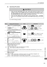
Setting the Tuning Mode 2 or 3

11

Press the 

 Key to complete the one-

parameter tuning operation. The display 

returns to the main menu of the utility 

function mode.

Note: The status display will always be RUN when the servomotor power is ON.

Step

Display after Operation

Keys

Operation

1

Press the 

 Key to view the main menu 

for the utility function mode.
Press the


or


Key to move 

through the list and select Fn203.

2

Press the


Key to display the moment of 

inertia ratio set in Pn103 at present. Move the 
digit with the 

 or 

 Key and change 

the value with the


or


Key.

3

Press the


Key to display the initial set-

ting screen for one-parameter tuning.

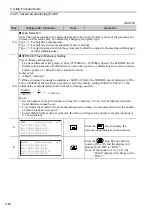
4

Press the


, , 

or


Key and 

set the items in steps 4-1 and 4-2.

4-1

„

Tuning Mode

Select the tuning mode. Select the tuning mode 2 or 3.

Tuning Mode = 2: Enables model following control and makes adjustments for positioning.

Tuning Mode = 3: Enables model following control, makes adjustments for positioning, and sup-

presses overshooting.

4-2

„

Type Selection

Select the type according to the machine element to be driven.

If there is noise or the gain does not increase, better results may be obtained by changing the rigidity 

type.

Type = 1: For belt drive mechanisms

Type = 2: For ball screw drive mechanisms [Factory setting]

Type = 3: For rigid systems in which the servomotor is directly coupled to the machine (without gear 

or other transmissions).

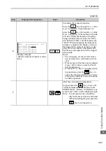
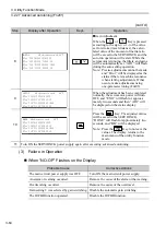
(cont’d)

Step

Display after Operation

Keys

Operation

㧾㨁㧺    ̆㧲㨁㧺㧯㨀㧵㧻㧺̆
㧲㨚㧞㧜㧞㧦㧾㨑㨒㧭㧭㨀
㧲㨚㧞㧜㧟㧦㧻㨚㨑㧼㨞㨙㨀㨡㨚
㧲㨚㧞㧜㧠㧦㧭㨂㨕㨎ޓ㧿㨡㨜
㧲㨚㧞㧜㧡㧦㨂㨕㨎ޓ㧿㨡㨜

㧮㧮ޓ  ޓ̆㧲㨁㧺㧯㨀㧵㧻㧺̆
㧲㨚㧞㧜㧞㧦㧾㨑㨒㧭㧭㨀
㧲㨚㧞㧜㧟㧦㧻㨚㨑㧼㨞㨙㨀㨡㨚
㧲㨚㧞㧜㧠㧦㧭㨂㨕㨎ޓ㧿㨡㨜
㧲㨚㧞㧜㧡㧦㨂㨕㨎ޓ㧿㨡㨜


̆


㨚̆


Status Display


̆


㨚̆

㧿


̆


㨚̆

㧿


Summary of Contents for JUSP-OP05A-1-E

Page 1: ...odel JUSP OP05A 1 E V Series AC Servo Drives USER S MANUAL Operation of Digital Operator MANUAL NO SIEP S800000 55B Introduction Parameter Monitor Modes Utility Function Mode Parameter Copy Mode 1 2 3 4 ...

Page 2: ...t liability is assumed with respect to the use of the information contained herein Moreover because Yaskawa is constantly striving to improve its high quality products the information contained in this manual is subject to change without notice Every precaution has been taken in the preparation of this manual Nevertheless Yaskawa assumes no responsibility for errors or omissions Neither is any lia...

Page 3: ...terms used in this manual Specific technical terms Different technical terms are used for rotational servomotors and linear servomotors and the terms for rotational servomotors are used in this manual Term Meaning Cursor Input position indicated by digital operator Servomotor Σ V Series SGMJV SGMAV SGMPS SGMGV SGMSV or SGMCS Direct Drive servomotor SERVOPACK Σ V Series SGDV SERVOPACK Servo Drive A...

Page 4: ... Wiring Trial operation Trial Operation and Servo Adjustment Inspec tion and Mainte nance Σ V series Catalog KAEP S800000 42 9 9 9 Σ V series User s Manual Setup Rotational Motor SIEP S800000 43 9 9 Σ V series User s Manual Setup Linear Motor SIEP S800000 44 9 9 Σ V series User s Manual Design and Maintenance Rotational Motor Analog and Pulse SIEP S800000 45 9 9 9 9 Σ V series User s Manual Design...

Page 5: ...eries User s Manual MECHATROLINK II Command SIEP S800000 54 9 9 9 Σ Vseries AC SERVOPACK SGDV Safety Precautions TOBP C710800 10 9 9 9 AC SERVOMOTOR Safety Precautions TOBP C230200 00 9 9 Manuals SERVOPACKs Servomotors and Peripheral Devices Ratings and Charac teristics System Design Panel Configura tion and Wiring Trial operation Trial Operation and Servo Adjustment Inspec tion and Mainte nance ...

Page 6: ... injury Indicates precautions that if not heeded could result in relatively serious or minor injury damage to the product or faulty operation In some situations the precautions indicated could have serious consequences if not heeded Indicates prohibited actions that must not be performed For example this symbol would be used to indicate that fire is prohibited as follows Indicates compulsory actio...

Page 7: ...ersonal injury The output range of the rotational serial data for the Σ V absolute position detecting system is different from that of earlier systems for 12 bit and 15 bit encoders As a result the infinite length positioning system of the Σ Series must be changed for use with products in the Σ V Series The multiturn limit value need not be changed except for special applica tions Changing it inap...

Page 8: ...onnect the ground terminal according to local electrical codes 100 Ω or less for a SERVOPACK with a 100 V 200 V power supply 10 Ω or less for a SERVOPACK with a 400 V power supply Improper grounding may result in electric shock or fire Installation disassembly or repair must be performed only by authorized personnel Failure to observe this warning may result in electric shock or injury The person ...

Page 9: ...ed and methods other than fumigation must be used Example Heat treatment where materials are kiln dried to a core temperature of 56 C for 30 minutes or more If the electronic products which include stand alone products and products installed in machines are packed with fumigated wooden materials the electrical components may be greatly damaged by the gases or fumes resulting from the fumigation pr...

Page 10: ... SERVOPACK power ON until all wiring including the main circuit terminal blocks has been completed Remove detachable main circuit terminals from the SERVOPACK prior to wiring Insert only one power line per opening in the main circuit terminals Make sure that no part of the core wire comes into contact with i e short circuits adjacent wires Install a battery at either the host controller or the SER...

Page 11: ...ecting it Failure to observe this caution may damage the battery the SERVOPACK or servomotor or cause an explosion Wiring or inspection must be performed by a technical expert Use a 24 VDC power supply with double insulation or reinforced insulation CAUTION ...

Page 12: ...ecessary precautions Failure to observe this caution may result in damage to the equipment When using the servomotor for a vertical axis install safety devices to prevent workpieces from falling due to alarms or overtravels Set the servomotor so that it will stop in the zero clamp state when overtravel occurs Failure to observe this caution may cause workpieces to fall due to overtravel When not u...

Page 13: ...t in damage to the equipment CAUTION When disposing of the products treat them as ordinary industrial waste Observe the following general precautions to ensure safe application The products shown in illustrations in this manual are sometimes shown without covers or protective guards Always replace the cover or protective guard as specified first and then operate the products in accordance with the...

Page 14: ...ed product in a manner in which it was not originally intended 5 Causes that were not foreseeable with the scientific and technological understand ing at the time of shipment from Yaskawa 6 Events for which Yaskawa is not responsible such as natural or human made disasters 2 Limitations of Liability 1 Yaskawa shall in no event be responsible for any damage or loss of opportunity to the customer th...

Page 15: ...operty Systems that require a high degree of reliability such as systems that supply gas water or electricity or systems that operate continuously 24 hours a day Other systems that require a similar high degree of safety 4 Never use the product for an application involving serious risk to life or property without first ensuring that the system is designed to secure the required level of safety wit...

Page 16: ...Analog Speed Torque Reference Offset Fn009 3 22 3 2 9 Manual Servo tuning of Speed Reference Offset Fn00A 3 24 3 2 10 Manual Servo tuning of Torque Reference Offset Fn00B 3 26 3 2 11 Offset Adjustment of Analog Monitor Output Fn00C 3 28 3 2 12 Gain Adjustment of Analog Monitor Output Fn00D 3 30 3 2 13 Automatic Offset Signal Adjustment of the Motor Current Detection Signal Fn00E 3 32 3 2 14 Manual...

Page 17: ...arameter Tuning Fn203 3 71 3 2 30 Anti Resonance Control Adjustment Function Fn204 3 79 3 2 31 Vibration Suppression Function Fn205 3 87 3 2 32 EasyFFT Fn206 3 91 3 2 33 Online Vibration Monitor Fn207 3 95 4 Parameter Copy Mode 4 1 4 1 Outline 4 2 4 2 Operations 4 3 4 2 1 Read out Parameters from SERVOPACK SERVO OP 4 3 4 2 2 Write in Parameters OP SERVO 4 6 4 2 3 Verify Parameters VERIFY 4 9 4 2 4...

Page 18: ...1 1 1 Introduction 1 Introduction 1 1 Part Names and Functions 1 3 1 2 Switching Mode 1 5 ...

Page 19: ...are used with Σ III SERVOPACKs A special connector JZSP CVS05 A3 E is required to use these operators with Σ V SERVOPACKs For details refer to Σ V Series User s Manual Setup Rotational Motor Manual No SIEP S800000 43 Insert securely to the CN3 connector of the SERVOPACK SGDV SERVOPACK JUSP OP05A 1 E Digital Operator VCMP SVON COIN TGON REF CHARGE ALARM DATA JOG SVON SCROLL MODE SET RESET SERVO REA...

Page 20: ...s VCMP SVON COIN TGON REF CHARGE ALARM DATA JOG SVON SCROLL MODE SET RESET SERVO READ WRITE SERVO YASKAWA DIGITAL OPERATOR JUSP OP05A 1 E Name Function SVON Lit when the servo is ON Unlit when the servo is OFF COIN VCMP Lit when positioning is completed Lit when the speed is coincident TGON Lit while the servomotor is running REF Position control Lit when the reference pulse is input Speed control...

Page 21: ...between the servo ON and servo OFF signals while executing a utility function such as a JOG operation or advanced autotuning Moves the cursor to left or right in parameter monitor mode Switches between parameters Pn and monitors Un Increases or decreases the parameter number setting data monitor number and utility function number Rotates the servomotor in a forward or reverse direction at a JOG op...

Page 22: ... Monitor Modes Parameter Functions Sets and displays the parameters of the SERVOPACK Monitoring Functions Shows the numerical values and signal statuses that indicate the internal data speed position and torque of the SERVOPACK The figure to the left shows the monitoring function screen Utility Function Mode Sets up the SERVOPACK adjusting the servo gains and maintains the SERVOPACK Parameter Copy...

Page 23: ...owing communications error codes are displayed These errors may be caused by incorrect connector connection Check the connection and correct it Then turn the power OFF and ON If the communications error message still appears replace the digital operator or the SERVOPACK C P F 0 0 C O M E R R O P S V C P F 0 1 C O M E R R O P S V ...

Page 24: ...rameter Monitor Modes 2 Parameter Monitor Modes 2 1 Parameter Mode 2 2 2 1 1 Parameter Setting 2 2 2 1 2 Parameter Classification 2 6 2 2 Monitor Mode 2 7 2 2 1 Monitor Items 2 7 2 2 2 Monitor Mode Display 2 10 ...

Page 25: ...f parameter Pn000 2 1 1 Parameter Setting 1 Operation Example 1 Setting the Parameters for Selecting Functions There are some parameters which require the setting of each digit such as Pn000 function selection basic switch and Pn001 function selection application switch 1 This example shows the operation procedure to set 1 reverse rotation for Pn000 0 motor direction selection Step Display after O...

Page 26: ...he first digit of Pn 000 0 6 Press the Key The new setting of Pn000 is written to the SERVOPACK The cursor moves to the parameter number side and the warning A 941 is displayed 7 To enable the change in the setting turn the power OFF and ON again Step Display after Operation Keys Operation B B P R M M O N P n 0 0 0 n 0 0 0 0 U n 0 0 2 0 0 0 0 0 0 U n 0 0 8 0 0 0 0 0 0 0 0 0 0 0 U n 0 0 D 0 0 0 0 0...

Page 27: ...the setting side to the position of the first digit of Pn304 B B P R M M O N U n 0 0 0 0 0 0 0 0 0 U n 0 0 2 0 0 0 0 0 0 U n 0 0 8 0 0 0 0 0 0 0 0 0 0 0 U n 0 0 D 0 0 0 0 0 0 0 0 0 0 0 B B P R M M O N U n 0 0 0 0 0 0 0 0 0 U n 0 0 2 0 0 0 0 0 0 U n 0 0 8 0 0 0 0 0 0 0 0 0 0 0 U n 0 0 D 0 0 0 0 0 0 0 0 0 0 0 B B P R M M O N P n 0 0 0 n 0 0 0 0 U n 0 0 2 0 0 0 0 0 0 U n 0 0 8 0 0 0 0 0 0 0 0 0 0 0 U...

Page 28: ...y five times to change the setting to 1000 9 Press the Key to write the set tings The cursor moves to the parameter number side Step Display after Operation Keys Operation B B P R M M O N P n 3 0 4 0 0 5 0 0 U n 0 0 2 0 0 0 0 0 0 U n 0 0 8 0 0 0 0 0 0 0 0 0 0 0 U n 0 0 D 0 0 0 0 0 0 0 0 0 0 0 B B P R M M O N P n 3 0 4 0 1 0 0 0 U n 0 0 2 0 0 0 0 0 0 U n 0 0 8 0 0 0 0 0 0 0 0 0 0 0 U n 0 0 D 0 0 0 ...

Page 29: ...ons for opera tion and the other type is required for tuning parameters that are required to adjust servomotor characteristics Classification Meaning Display Method Setting Method Setup Parameters Parameters required for setup Always displayed Factory setting Pn00B 0 0 Set each parameter individually Tuning Parameters Parameters for tun ing control gain and other parameters Set Pn00B 0 to 1 There ...

Page 30: ... error amount displayed only in position control mode Reference unit Un009 Accumulated load ratio in percentage to the rated torque effective torque in cycle of 10 sec onds Un00A Regenerative load ratio in percentage to the processable regenerative power regenerative power consumption in cycle of 10 seconds Un00B Power consumed by DB resistance in percent age to the processable power at DB activat...

Page 31: ...itch index Scale pitch Un084 10Un085 pm Parameter No Content of Display Unit Display LED Number Input Terminal Name Signal Name Factory Setting 1 CN1 40 can be allocated S ON Servo ON input 2 CN1 41 can be allocated P CON Proportional operation refer ence input 3 CN1 42 can be allocated P OT Forward run prohibited input 4 CN1 43 can be allocated N OT Reverse run prohibited input 5 CN1 44 can be al...

Page 32: ...tory Setting 1 CN1 31 C 32 cannot be allocated ALM Servo alarm output 2 CN1 25 C 26 can be allocated COIN Positioning completion output or V CMP Speed coincidence output 3 CN1 27 C 28 can be allocated TGON Detection during servomotor rotation output 4 CN1 29 C 30 can be allocated S RDY Servo ready output 5 CN1 37 cannot be allocated AL01 Alarm code output 6 CN1 38 cannot be allocated AL02 Alarm co...

Page 33: ... signal monitor Step Display after Operation Keys Operation 1 Press the Key to select the parameter monitor mode 2 Press the Key once to move the cursor to the fourth line 3 or Press the or Key to dis play Un006 Output signal monitor 4 Press the Key once to move the cursor to the line above B B P R M M O N U n 0 0 0 0 0 0 0 0 0 U n 0 0 2 0 0 0 0 0 0 U n 0 0 8 0 0 0 0 0 0 0 0 0 0 0 U n 0 0 D 0 0 0 ...

Page 34: ... the Key The LED on the key blinks and the dis play with selected items is saved Note Do not turn OFF the SERVO PACK s control power while saving Step Display after Operation Keys Operation B B P R M M O N U n 0 0 0 0 0 0 0 0 0 U n 0 0 2 0 0 0 0 0 0 U n 0 0 5 U n 0 0 6 B B P R M M O N U n 0 0 0 0 0 0 0 0 0 U n 0 0 2 0 0 0 0 0 0 U n 0 0 5 U n 0 0 6 ...

Page 35: ...the Motor Current Detection Sig nal Fn00E 3 32 3 2 14 Manual Offset Signal Adjustment of the Motor Current Detection Signal Fn00F 3 34 3 2 15 Write Prohibited Setting Fn010 3 36 3 2 16 Servomotor Model Display Fn011 3 39 3 2 17 Software Version Display Fn012 3 41 3 2 18 Multiturn Limit Value Setting Change When a Multiturn Limit Disagree ment Alarm Occurs Fn013 3 42 3 2 19 Resetting Configuration ...

Page 36: ...3 Utility Function Mode 3 2 3 2 31 Vibration Suppression Function Fn205 3 87 3 2 32 EasyFFT Fn206 3 91 3 2 33 Online Vibration Monitor Fn207 3 95 ...

Page 37: ...08 Absolute encoder multiturn reset and encoder alarm reset Resets the absolute encoder alarm and resets the multiturn data to zero 9 9 Fn009 Automatic tuning of analog speed torque reference offset Adjusts automatically the speed or torque ana log reference offset 9 9 Fn00A Manual servo turning of speed reference offset Adjusts manually the speed reference offset 9 Fn00B Manual servo turning of t...

Page 38: ...idual option module 9 Fn01B Vibration detection level initialization Automatically adjusts the detection level of vibration alarm warning 9 Fn01E 3 Display of SERVO PACK and servomo tor ID Displays the model serial number and manu facturing date of the SERVOPACK and servo motor stored in the feedback option module Fn01F 3 Display of servomo tor ID in feedback option module Displays encoder ID Fn02...

Page 39: ...ores phase information of the motor from home position in the SERVO PACK 9 9 Fn200 Tuning less levels setting Sets the level of tuning less function 9 Fn201 Advanced autotuning Automatically sets servo gain and filter by automatic operation 9 9 Fn202 Advanced autotuning by reference Sets servo gains and filters automatically while the motor is running 9 Fn203 One parameter tuning Changes four serv...

Page 40: ...2 1 Alarm History Display Fn000 This function displays the last ten alarms that have occurred in the SERVOPACK The latest ten alarm numbers and time stamps can be checked Time Stamps A function that measures the ON times of the control power supply and main circuit power supply in 100 ms units and displays the total operating time when an alarm occurs The time stamp operates around the clock for a...

Page 41: ... Operation 1 Press the Key to view the main menu for the utility function mode Use the or Key to move through the list and select Fn000 2 Press the Key The display changes to the Fn000 execution display 3 Press the or Key to scroll through the alarm history The alarm his tory can be viewed 4 Press the Key The display returns to the main menu of the utility function mode 㧮㧮 ޓޓޓޓޓ 㧙㧲㨁㧺㧯㨀㧵㧻㧺㧙 㧲㨚㧞㧜㧣㧦㨂...

Page 42: ...irect drive motor the setting unit will be automatically changed to 0 1 min 1 2 Operating Procedure Use the following procedure The following example is given when the rotating direction of servomotor is set as Pn000 0 0 Forward rotation by forward reference CAUTION While the SERVOPACK is in JOG operation the overtravel function will be dis abled Consider the operating range of the machine when pe...

Page 43: ...ssed 8 After having confirmed the correct motion of servomotor press the Key The status display changes from RUN to BB and the servomotor power turns OFF cont d Step Display after Operation Keys Operation 㧮㧮 ޓޓޓޓޓޓޓޓޓޓ 㧙㧶㧻㧳㧙 㧼㨚㧟㧜㧠㧩㧜㧜㧡㧜㧜 ޓ 㨁㨚㧜㧜㧜㧩 ޓ 㧜㧜㧜㧜㧜 㨁㨚㧜㧜㧞㧩 ޓ 㧜㧜㧜㧜㧜 㨁㨚㧜㧜㧰㧩 ޓ 㧜㧜㧜㧜㧜㧜㧜㧜㧜㧜 㧮㧮 ޓޓޓޓޓޓޓޓޓޓ 㧙㧶㧻㧳㧙 㧼㨚㧟㧜㧠㧩㧜㧜㧡㧜㧜 ޓ 㨁㨚㧜㧜㧜㧩 ޓ 㧜㧜㧜㧜㧜 㨁㨚㧜㧜㧞㧩 ޓ 㧜㧜㧜㧜㧜 㨁㨚㧜㧜㧰㧩 ޓ 㧜㧜㧜㧜㧜㧜㧜㧜㧜㧜 㧮㧮 ޓޓޓޓޓޓޓޓޓޓ 㧙㧶㧻㧳㧙 㧼㨚㧟㧜㧠㧩㧜...

Page 44: ...ess the Key The display returns to the main menu of the utility function mode 10 Turn OFF the power and then turn it ON again cont d Step Display after Operation Keys Operation 㧮㧮 ޓޓޓޓޓ 㧙㧲㨁㧺㧯㨀㧵㧻㧺㧙 㧲㨚㧜㧜㧜㧦㧭㨘㨙 ޓ 㧴㨕㨟㨠㨛㨞㨥 㧲㨚㧜㧜㧞㧦㧶㧻㧳 㧲㨚㧜㧜㧟㧦㨆㧙㧿㨑㨍㨞㨏㨔 㧲㨚㧜㧜㧠㧦㧼㨞㨛㨓㨞㨍㨙 ޓ 㧶㧻㧳 ...

Page 45: ... the time of execution is 6 min 1 1 Preparation The following conditions must be met to perform the origin search The write prohibited setting Fn010 must not be set to write protect parameters The main circuit power supply must be ON All alarms must be cleared The hardwire baseblock HWBB must be disabled The servomotor power must be OFF CAUTION Perform origin searches without connecting the coupli...

Page 46: ...the servomotor Press the or Key until the motor stops If the origin search completed normally Complete is displayed on the right top on the screen 5 When the origin search is completed press the Key The status display changes from RUN to BB and the servomotor power turns OFF The display Complete changes to Z Search 㧮 㧮 㧲 㨁 㧺 㧯 㨀 㧵 㧻 㧺 㧲 㨚 㧜 㧜 㧞㧦㧶㧻㧳 㧲 㨚 㧜 㧜 㧟㧦㨆 㧿㨑㨍㨞㨏㨔 㧲 㨚 㧜 㧜 㧠㧦㧼㨞㨛㨓㨞㨍㨙 ޓ 㧶㧻㧳 㧲 㨚 㧜 ...

Page 47: ...Key The display returns to the main menu of the utility function mode 7 Turn OFF the power and then turn it ON again cont d Step Display after Operation Keys Operation 㧮 㧮 㧲 㨁 㧺 㧯 㨀 㧵 㧻 㧺 㧲 㨚 㧜 㧜 㧞㧦㧶㧻㧳 㧲 㨚 㧜 㧜 㧟㧦㨆 㧿㨑㨍㨞㨏㨔 㧲 㨚 㧜 㧜 㧠㧦㧼㨞㨛㨓㨞㨍㨙 ޓ 㧶㧻㧳 㧲 㨚 㧜 㧜 㧡㧦㧼㨞㨙 ޓ 㧵㨚㨕㨠 ...

Page 48: ...ust be met to perform the program JOG operation The write prohibited setting Fn010 must not be set to write protect parameters The main circuit power supply must be ON All alarms must be cleared The hardwire baseblock HWBB must be disabled The servomotor power must be OFF The travel distance and speed must be set correctly considering the machine opera tion range and safe operation speed There mus...

Page 49: ...lay changes from BB to RUN and the servomotor power turns ON 5 Press the forward movement start or reverse movement start Key according to the first move ment direction of the preset operation pattern The servomotor starts moving after the preset waiting time in Pn535 Note Pressing the Key again changes the status to BB baseblocked status and stops movement even during opera tion The settings can ...

Page 50: ...cond and then RUN is displayed Press the Key The servomotor becomes baseblocked status The dis play returns to the main menu of the utility function mode 7 After program JOG operation turn OFF the power and then turn ON again cont d Step Display after Operation Keys Operation 㧱㧺㧰 ޓޓޓޓޓ 㧙㧼㧾㧳 ޓ 㧶㧻㧳㧙 㧼㨚㧡㧟㧝㧩㧜㧜㧜㧟㧞㧣㧢㧤 㧼㨚㧡㧟㧟㧩㧜㧜㧡㧜㧜 㧼㨚㧡㧟㧠㧩㧜㧜㧝㧜㧜 ޓ 㧼㨚㧡㧟㧢㧩㧜㧜㧜㧝㧜 ...

Page 51: ...The servomotor power must be OFF 2 Operating Procedure Use the following procedure Be sure to initialize the parameter settings while the servo motor power is OFF After initialization turn OFF the power supply and then turn ON again to validate the settings Step Display after Operation Keys Operation 1 Press the Key to view the main menu for the utility function mode Use the or Key to move through...

Page 52: ...on is completed Parameter Init stops flashing and the status display changes as follows BB to DONE to BB Note Press the Key not to ini tialize parameters The display returns to the main menu of the utility function mode 4 Turn OFF the power and then turn it ON again to validate the new setting cont d Step Display after Operation Keys Operation 㧮㧮 ޓ 㧼㨍㨞㨍㨙㨑㨠㨑㨞 ޓ 㧵㨚㨕㨠 ޓޓ 㧿㨠㨍㨞㨠 ޓ 㧦㨇㧰㧭㨀㧭㨉 ޓޓ 㧾㨑㨠㨡㨞㨚㧦㨇㧿㧱...

Page 53: ...ration Keys Operation 1 Press the Key to view the main menu for the utility function mode Use the or Key to move through the list and select Fn006 2 Press the Key The display changes to the Fn006 execution dis play 3 Press the Key to clear the alarm history While clearing the data DONE is displayed in the status display After the data has been successfully cleared BB is displayed Note Press the Ke...

Page 54: ...celed with the ALM_CLR command Encoder backup error alarm A 810 Encoder checksum error alarm A 820 Any other alarms A 8 that monitor the inside of the encoder should be can celed by turning OFF the power 2 Preparation The following conditions must be met to setup the absolute encoder The write prohibited setting Fn010 must not be set to write protect parameters The servomotor power must be OFF CAU...

Page 55: ...Key to setup the abso lute encoder After completing the setup DONE is flashed for approxi mately one second and BB is dis played 5 Press the Key The display returns to the main menu of the utility function mode 6 Turn OFF the power and then turn it ON again to validate the new setting 㧮 㧮 㧲 㨁 㧺 㧯 㨀 㧵 㧻 㧺 㧲 㨚 㧜 㧜 㧢㧦㧭㨘㨙㧴㨕㨟㨠 㧯㨘㨞 㧲 㨚 㧜 㧜 㧤㧦㧹㨠㨡㨞㨚 㧯㨘㨞 㧲 㨚 㧜 㧜 㧥㧦㧾㨑㨒 㧭㨐㨖 㧲 㨚 㧜 㧜 㧭㧦㨂㨑㨘 㧭㨐㨖 㧮 㧮 㧹 㨡 㨘 㨠 㨕 㨠 ...

Page 56: ...itions must be met to adjust the offsets of speed or torque analog reference automatically The write prohibited setting Fn010 must not be set to write protect parameters The servomotor power must be OFF 2 Operating Procedure Use the following procedure Step Display after Operation Keys Operation 1 Set the analog voltage input to 0 V 2 Press the Key to view the main menu of the utility function mod...

Page 57: ...ce speed or torque offset DONE is displayed during the pro cessing and BB is displayed at the completion Press the Key not to execute the automatic adjustment The display returns to the main menu of the utility function mode cont d Step Display after Operation Keys Operation B B R e f A d j u s t S t a r t D A T A R e t u r n S E T ...

Page 58: ... prohibited setting Fn010 must not be set to write protect parameters The main circuit power supply must be ON All alarms must be cleared The hardwire baseblock HWBB must be disabled When an absolute encoder is used the SEN signal is ON high level 2 Operating Procedure Use the following procedure Step Display after Operation Keys Operation 1 Set the analog voltage input to 0 V 2 Press the Key to v...

Page 59: ... tus display shows DONE for one sec ond 7 Press the Key The display returns to the main menu of the utility function mode cont d Step Display after Operation Keys Operation R U N V e l o c i t y A d j u s t Z A D J V 0 0 0 1 2 V r e f 0 0 0 0 0 R U N V e l o c i t y A d j u s t Z A D J V 0 0 0 1 5 V r e f 0 0 0 0 0 R U N F U N C T I O N F n 0 0 9 R e f A d j F n 0 0 A V e l A d j F n 0 0 B T r q A...

Page 60: ... circuit power supply must be ON All alarms must be cleared The hardwire baseblock HWBB must be disabled When an absolute encoder is used the SEN signal is ON high level 2 Operating Procedure Use the following procedure Step Display after Operation Keys Operation 1 Set the analog voltage input to 0 V 2 Press the Key to view the main menu of the utility function mode Use the or Key to move through ...

Page 61: ... tus display shows DONE for one sec ond 7 Press the Key The display returns to the main menu of the utility function mode cont d Step Display after Operation Keys Operation R U N T o r q u e A d j u s t Z A D J T 0 0 0 0 7 T r e f 0 0 0 0 0 R U N T o r q u e A d j u s t Z A D J T 0 0 0 0 7 T r e f 0 0 0 0 0 R U N F U N C T I O N F n 0 0 A V e l A d j F n 0 0 B T r q A d j F n 0 0 C M o n Z e r o A...

Page 62: ...set to write protect parameters 2 Operating Procedure Use the following procedure Step Display after Operation Keys Operation 1 Press the Key to view the main menu for the utility function mode Use the or Key to move through the list and select Fn00C 2 Press the Key The display changes to the Fn00C execution dis play 3 Press the or Key to adjust the offset of CH1 torque refer ence monitor Adjust t...

Page 63: ...The adjustment results are saved in the SERVOPACK and the status display shows DONE for one second The status display then returns to show BB again 7 Press the Key The display returns to the main menu of the utility function mode cont d Step Display after Operation Keys Operation 㧮㧮 ޓޓޓޓޓ 㧙㨆㨑㨞㨛 ޓ 㧭㧰㧶㧙 㧯㧴㧝㧩㧙㧜㧜㧜㧜㧡 㨁㨚㧜㧜㧞㧩 ޓ 㧜㧜㧜㧜㧜 㧯㧴㧞㧩 ޓ 㧜㧜㧜㧜㧢 㨁㨚㧜㧜㧜㧩 ޓ 㧜㧜㧜㧜㧜 㧮㧮 ޓޓޓޓޓ 㧙㨆㨑㨞㨛 ޓ 㧭㧰㧶㧙 㧯㧴㧝㧩㧙㧜㧜㧜㧜㧡 㨁㨚㧜㧜㧞㧩 ޓ 㧜...

Page 64: ... Fn005 1 Preparation The following condition must be met to adjust the gain of the analog monitor output The write prohibited setting Fn010 must not be set to write protect parameters 2 Operating Procedure Use the following procedure Step Display after Operation Keys Operation 1 Press the Key to view the main menu for the utility function mode Use the or Key to move through the list and select Fn0...

Page 65: ...n the SERVOPACK and the status display shows DONE for one second The status display then returns to show BB again 7 Press the Key The display returns to the main menu of the utility function mode cont d Step Display after Operation Keys Operation 㧮㧮 ޓޓޓޓޓ 㧙㧳㨍㨕㨚 ޓ 㧭㧰㧶㧙 㧯㧴㧝㧩 ޓ 㧜㧜㧝㧞㧡 㨁㨚㧜㧜㧞㧩 ޓ 㧜㧜㧜㧜㧜 㧯㧴㧞㧩㧙㧜㧜㧝㧞㧡 㨁㨚㧜㧜㧜㧩 ޓ 㧜㧜㧜㧜㧜 㧮㧮 ޓޓޓޓޓ 㧙㧳㨍㨕㨚 ޓ 㧭㧰㧶㧙 㧯㧴㧝㧩 ޓ 㧜㧜㧝㧞㧡 㨁㨚㧜㧜㧞㧩 ޓ 㧜㧜㧜㧜㧜 㧯㧴㧞㧩㧙㧜㧜㧝㧞㧡 㨁㨚㧜㧜㧜㧩 ޓ 㧜㧜㧜㧜㧜 㧮...

Page 66: ...power supply must be ON All alarms must be cleared The hardwire baseblock HWBB must be disabled When an absolute encoder is used the SEN signal is ON high level The servomotor power must be OFF 2 Operating Procedure Use the following procedure Be sure to perform this function while the servomotor power is OFF Execute the automatic offset adjustment if the torque rip ple is too big when compared wi...

Page 67: ...ment is completed the status display shows DONE for one second The status display then returns to show BB again Note Press the Key to cancel the automatic adjustment The display returns to the main menu of the utility function mode cont d Step Display after Operation Keys Operation 㧮㧮 㧭㨡㨠㨛 ޓ 㧻㨒㨒㨟㨑㨠㧙㧭㧰㧶 ޓޓ 㧿㨠㨍㨞㨠 ޓ 㧦㨇㧰㧭㨀㧭㨉 ޓ 㨛㨒 ޓ 㧹㨛㨠㨛㨞 ޓ 㧯㨡㨞㨞㨑㨚㨠 ޓޓ 㧾㨑㨠㨡㨞㨚㧦㨇㧿㧱㨀㨉 ...

Page 68: ...ction is executed carelessly it may worsen the char acteristics Observe the following precautions when performing manual servo tuning Run the servomotor at a speed of approximately 100 min 1 Adjust the offset while monitoring the torque reference with the analog monitor until the ripple of torque reference monitor s waveform is minimized Adjust the phase U and phase V offset amounts alter nately s...

Page 69: ...ions cannot reduce the torque ripple any more Then perform the same operation by adjusting by smaller amount 7 Press the Key to save the result of adjustment in the SERVOPACK When the saving is completed the sta tus display shows DONE for one sec ond The status display then returns to show RUN again 8 Press the Key The display returns to the main menu of the utility function mode cont d Step Displ...

Page 70: ...ram JOG operation Cannot be executed Fn005 Initializing parameter settings Cannot be executed Fn006 Clearing alarm history Cannot be executed Fn008 Absolute encoder multiturn reset and encoder alarm reset Cannot be executed Fn009 Automatic tuning of analog speed torque ref erence offset Cannot be executed Fn00A Manual servo turning of speed reference offset Cannot be executed Fn00B Manual servo tu...

Page 71: ...be executed Fn030 Software reset Executable Fn080 Polarity detection Cannot be executed Fn200 Tuning less levels setting Cannot be executed Fn201 Advanced autotuning Cannot be executed Fn202 Advanced autotuning by reference Cannot be executed Fn203 One parameter tuning Cannot be executed Fn204 Anti resonance control adjustment function Cannot be executed Fn205 Vibration suppression function Cannot...

Page 72: ... or Key to select one of the following settings P 0000 Write permitted Factory set ting P 0001 Write prohibited 4 Press the Key The setting value is written into the SERVOPACK and the status display changes as follows DONE to BB Note Saved settings will be enabled after the SERVOPACK is restarted 5 Turn OFF the power and then turn it ON again to validate the new setting B B F U N C T I O N F n 0 0...

Page 73: ... multi turning can only be used with a direct drive motor Press the Key The display changes to the Fn011 execution display and shows the information about the servomotor and encoder being used 3 Press the Key The display returns to the main menu of the utility function mode 㧮㧮 ޓޓޓޓ 㧙㧲㨁㧺㧯㨀㧵㧻㧺㧙 㧲㨚㧜㧝㧜㧦㧼㨞㨙 ޓ 㧼㨞㨛㨠㨑㨏㨠 㧲㨚㧜㧝㧟㧦㧹㨠㨡㨞㨚㧸㨙㧿㨑㨠 ޓ 㧲㨚㧜㧝㧞㧦㧿㨛㨒㨠 ޓ 㨂㨑㨞 㧲㨚㧜㧝㧝㧦㧹㨛㨠㨛㨞 ޓ 㧵㨚㨒㨛 Servomotor capacity Servomotor ...

Page 74: ...r capacity Servomotor input voltage 00 01 E N C O R D E R 0 1 8 b i t B B M o t o r l n f o T Y P E 4 0 A C 2 0 0 V 4 0 0 W Servomotor Model Encoder Type Incremental 12 8 4096 256 No Number of Divisions on the Linear Scale 40 Linear servomotor Absolute value Number of Divisions ...

Page 75: ...ction mode Use the or Key to move through the list and select Fn012 2 Press the Key The display changes to the Fn012 execution dis play The software versions of the SERVO PACK and the connected encoder will appear Note If the servomotor is not con nected Not connect is dis played 3 Press the Key The display returns to the main menu of the utility function mode 㧮㧮 ޓޓޓޓޓ 㧙㧲㨁㧺㧯㨀㧵㧻㧺㧙 㧲㨚㧜㧝㧠㧦㧻㨜㨠 ޓ 㧵㨚㨕㨠 ...

Page 76: ...ollowing procedure Alarm Display Alarm Name Alarm Output Meaning A CC0 Multiturn Limit Disagreement OFF H Different multiturn limits have been set in the encoder and SERVOPACK Step Display after Operation Keys Operation 1 Press the Key to view the main menu for the utility function mode Use the or Key to move through the list and select Fn013 2 Press the Key The display changes to the Fn013 exe cu...

Page 77: ...urns to the main menu of the utility function mode 5 Turn OFF the power and then turn it ON again to validate the new setting cont d Step Display after Operation Keys Operation 㧭 㧚 㧯 㧯 㧜 㧲 㨁 㧺 㧯 㨀 㧵 㧻 㧺 㧲 㨚 㧜 㧝 㧞㧦㧿㨛㨒㨠 㨂㨑㨞 㧲 㨚 㧜 㧝 㧟㧦㧹㨠㨡㨞㨚㧸㨙㧿㨑㨠 㧲 㨚 㧜 㧝 㧠㧦㧻㨜㨠 㧵㨚㨕㨠 㧲 㨚 㧜 㧝 㧮㧦㨂㨕㨎㨘A㨢㨘 㧵㨚㨕㨠 ...

Page 78: ...odule The write prohibited setting Fn010 must not be set to write protect parameters 2 Operating Procedure Use the following procedure Step Display after Operation Keys Operation 1 Press the Key to view the main menu for the utility function mode Use the or Key to move through the list and select Fn014 2 Press the Key The display changes to the Fn014 execution dis play 3 Press the or Key to select...

Page 79: ... 3 6 Press the Key The display returns to the main menu of the utility function mode 7 Turn OFF the power and then turn it ON again to validate the new setting cont d Step Display after Operation Keys Operation B B O p t I n i t 0 2 S a f e t y O p t 0 3 F e e d b a c k O p t 0 1 C o m m a n d O p t R U N F U N C T I O N F n 0 1 3 M t u r n L m S e t F n 0 1 4 O p t I n i t F n 0 1 B V i b l v l I...

Page 80: ...rning A 911 is not output correctly when a vibration at the factory setting of the vibration detec tion level Pn312 is detected In other cases it is not necessary to use this func tion The vibration alarm or warning detection sensibility differs depending on the machine conditions In this case fine tune the setting of the vibration detection sensitivity Pn311 using the above detection level formul...

Page 81: ...ut to execute this function Execute this function under the operating condition for which the vibration detection level should be set Execute this function while the motor speed reaches at least 10 of its maximum Step Display after Operation Keys Operation 1 Press the Key to view the main menu for the utility function mode Use the or Key to move through the list and select Fn01B 2 Press the Key Th...

Page 82: ...ew setting of Pn312 becomes enabled 5 Press the Key The display returns to the main menu of the utility function mode cont d Step Display after Operation Keys Operation L e v e l I n i t R U N V i b r a t i o n D e t e c t D O N E R U N F U N C T I O N F n 0 1 4 O p t I n i t F n 0 1 B V i b l v l I n i t F n 0 1 E S v M o t O p I D F n 0 1 F F B O p M o t I D ...

Page 83: ...e Displayed SERVOPACK ID SERVOPACK model SERVOPACK serial number SERVOPACK manufacturing date SERVOPACK input voltage V Maximum applicable motor capacity W Maximum applicable motor rated current Arms Servomotor ID Servomotor model Servomotor order number Servomotor manufacturing date Servomotor input voltage V Servomotor capacity W Servomotor rated current Arms Encoder ID Encoder model Encoder ser...

Page 84: ...ew other information 5 Press the Key The display returns to the main menu of the utility function mode R U N F U N C T I O N F n 0 1 B V i b l v l I n i t F n 0 1 E S v M o t O p I D F n 0 1 F F B O p M o t I D F n 0 2 0 S O r i g S e t B B S v M o t O p I D D r i v e r S G D V R 7 0 A 0 1 A D 0 0 2 4 1 2 3 4 5 9 0 0 0 1 0 2 0 4 2 0 0 V 5 0 W Serial number Manufacturing date SERVOPACK model Input ...

Page 85: ...el Encoder serial number Encoder type resolution Two types of resolution display avail able Number of bits and number of pulses rev Parameter File ID Parameter file source ID 14 characters Parameter file version 4 digits hexadecimal display Step Display after Operation Keys Operation 1 Press the Key to view the main menu for the utility function mode Use the or Key to move through the list and sel...

Page 86: ...view other information 5 Press the Key The display returns to the main menu of the utility function mode cont d Step Display after Operation Keys Operation B B F B O p M o t I D E n c o d e r U T S T H U 1 3 D B S e r i a l N o 1 3 b i t I N C Encoder type resolution Encoder model B B F B O p M o t I D P r m ޓ F i l e Y E C 0 0 0 0 0 V e r s i o n 0 0 0 0 Parameter file version Origin parameter fi...

Page 87: ...941 will not be shown and BB will be displayed instead Step Display after Operation Keys Operation 1 Press the Key to view the main menu for the utility function mode Use the or Key to move through the list and select Fn020 2 Press the Key The display changes to the Fn020 execution display 3 Press the or Key to ORGSET5 4 Press the key to start setting the ori gin The message Scale Origin Set flash...

Page 88: ...on after the servomotor power is OFF This function resets the SERVOPACK independently of host controller The SERVOPACK carries out the same processing as when the power supply is turned ON and outputs the ALM signal The status of other output signals may be forcibly changed Step Display after Operation Keys Operation 1 Press the Key to view the main menu for the utility function mode Use the or Ke...

Page 89: ...the power is turned ON will be displayed Then the mode changes to the parameter monitor display mode 6 Press the Key The display returns to the main menu of the utility function mode cont d Step Display after Operation Keys Operation B B S o f t w a r e R e s e t F i l e F i r s t L o a d i n g P l e a s e W a i t B B F U N C T I O N F n 0 2 0 S O r i g S e t F n 0 3 0 S o f t R e s e t F n 0 8 0 ...

Page 90: ...ess the or Key to move through the list and select Fn080 2 Press the Key The display changes to the Fn080 exe cution display To adjust the level Press the or Key to move the cursor from to the digit Press the or Key to change the value of each digit 3 Press the Key The display shown on the left appears 4 Press the Key The linear servo motor will be in servo ON status and the polarity detection wil...

Page 91: ...t appears 6 Press the Key The display returns to the main menu of the utility function mode cont d Step Display after Operation Keys Operation B B M a g n e t i c P o l e D e t e c t R e t u r n S E T B B F U N C T I O N F n 0 3 0 S o f t R e s e t F n 0 8 0 P o l e D e t e c t F n 2 0 0 T u n e L v l S e t F n 2 0 1 A A T ...

Page 92: ...on in a state where the SERVO PACK can come to an emergency stop at any time Step Display after Operation Keys Operation 1 Press the Key to view the main menu for the utility function mode Use the or Key to move through the list select Fn200 2 Press the Key to display the load level of the tuning less mode setting screen Notes If the response waveform causes over shooting or if the load moment of ...

Page 93: ... is 4 Notes Vibration may occur if the rigidity level is too high Lower the rigidity level if vibration occurs If a high frequency noise is heard press the Key to automatically set a notch filter to the vibration frequency 5 Press the Key DONE will flash for approximately two seconds and then RUN will be displayed The settings are saved in the SERVOPACK 6 Press the Key The display returns to the m...

Page 94: ...y must be ON There must be no overtravel The servomotor power must be OFF The control method must not be set to torque control The gain selection switch must be in manual switching mode Pn139 0 0 Gain setting 1 must be selected The test without a motor function must be disabled Pn00C 0 0 All alarms and warning must be cleared The hardwire baseblock HWBB must be disabled The write prohibited settin...

Page 95: ...initial setting screen for advanced autotuning 3 Press the or Key and set the items in steps 3 1 to 3 4 3 1 Calculating Moment of Inertia Select the mode to be used Usually set Jcalc to ON Jcalc ON Moment of inertia calculated Factory setting Jcalc OFF Moment of inertia not calculated Note If the moment of inertia ratio is already known from the machine specifications set the value in Pn103 and se...

Page 96: ...istance will be set to 800000 If the electronic gear ratio is set to the factory setting Pn20E 4 Pn210 1 the initial value is calculated as shown with the following equation Notes Set the number of motor rotations to at least 0 5 otherwise Error will be displayed and the travel distance cannot be set To calculate the moment of inertia and ensure precise tuning it is recommended to set the number o...

Page 97: ...ly Notes The wrong key for the set travel direc tion is pressed the calculation will not start If the moment of inertia is not calculated Jcalc OFF the set value for Pn103 will be displayed If NO OP or Error is displayed dur ing operation press the Key to cancel the function Refer to 3 Failure in Operation and take a corrective action to enable operation 7 After the servomotor is temporarily stopp...

Page 98: ...lay 10 Press the Key The adjusted values will be saved in the SERVOPACK DONE will flash for approximately two seconds and BB will be displayed Note Press the Key to not save the values The display returns to the main menu of the utility function mode 11 Turn ON the SERVOPACK power supply again after executing advanced autotuning Probable Cause Corrective Actions The main circuit power supply was O...

Page 99: ... the minimum adjustable travel distance Increase the travel distance It is recommended to set the number of motor rotations to around 3 The positioning completed signal COIN did not turn ON within approximately 10 seconds after positioning adjustment was completed The positioning completed width is too narrow or pro portional control P control is being used Increase the set value for Pn522 Set V_P...

Page 100: ...it Double the set value of the moment of inertia calculating start level Pn324 Err5 While calculating the moment of inertia the speed control was set to proportional control by setting V_PPI in the Option field to 1 Operate the SERVOPACK with PI con trol while calculating the moment of inertia cont d Error Display Probable Cause Corrective Actions ...

Page 101: ... The message NO OP indicating that the settings are not appropriate will be displayed if all of the following conditions are not met The main circuit power supply must be ON All alarms must be cleared The hardwire baseblock HWBB must be disabled When an absolute encoder is used the SEN signal is ON high level There must be no overtravel The servomotor power must be OFF The position control must be...

Page 102: ...justments for positioning Factory setting Mode 3 Makes adjustments for positioning giving priority to overshooting suppression 3 2 Type Selection Select the type according to the machine element to be driven If there is noise or the gain does not increase better results may be obtained by changing the rigidity type Type 1 For belt drive mechanisms Type 2 For ball screw drive mechanisms Factory set...

Page 103: ...two seconds and RUN will be displayed Note Press the Key to not save the values The display returns to the main menu of the utility function mode 9 Turn ON the SERVOPACK power supply again after executing advanced autotuning by reference cont d Step Display after Operation Keys Operation 㧾㨁㧺 㧭 㨐 㨢 㨍 㨚 㨏 㨑 㨐 㧭㨀 㧼 㨚 㧝 㧜 㧟 㧩 㧜 㧜 㧟 㧜 㧜 㧼 㨚 㧝 㧜 㧜 㧩 㧜 㧜 㧠 㧜 㧜 㧼 㨚 㧝 㧜 㧝 㧩 㧜 㧜 㧞 㧜 㧜㧜 㧼 㨚 㧝 㧠 㧝 㧩㧜 㧜 㧡 㧜 㧜 ...

Page 104: ...B function Error Probable Cause Corrective Actions The gain adjustment was not successfully completed Machine vibration is occur ring or the positioning com pleted signal COIN is turning ON and OFF when the servomotor is stopped Increase the set value for Pn522 Change the mode from 2 to 3 If machine vibration occurs suppress the vibration with the anti resonance control adjust ment function and th...

Page 105: ...notch filter Friction compensation Anti resonance control 1 Preparation The following conditions must be met to perform the one parameter tuning The message NO OP indicating that the settings are not appropriate will be dis played if all of the following conditions are not met The test without a motor function must be disabled Pn00C 0 0 The write prohibited setting Fn010 must not be set to write p...

Page 106: ...led and one parameter tuning will be used as the tuning method for applications other than positioning When the tuning mode is set to 2 or 3 the model following control will be enabled and it can be used for tuning for positioning Make sure that the moment of inertia ratio Pn103 is set correctly using advanced autotuning before beginning operation CAUTION When using the MP2000 Series with phase co...

Page 107: ...e Selection Select the type according to the machine element to be driven If there is noise or the gain does not increase better results may be obtained by changing the rigidity type Type 1 For belt drive mechanisms Type 2 For ball screw drive mechanisms Factory setting Type 3 For rigid systems in which the servomotor is directly coupled to the machine without gear or other transmissions 5 If the ...

Page 108: ...rner If the vibration is great the vibration fre quency will be detected automatically even if the Key is not pressed and a notch filter or an anti resonance con trol will be set 9 Press the Key A confirmation screen will be displayed after LEVEL adjustment 10 Press the Key to save the adjusted values After the data is saved DONE will flash for approximately two seconds and then RUN will be displa...

Page 109: ...ect the tuning mode 2 or 3 Tuning Mode 2 Enables model following control and makes adjustments for positioning Tuning Mode 3 Enables model following control makes adjustments for positioning and sup presses overshooting 4 2 Type Selection Select the type according to the machine element to be driven If there is noise or the gain does not increase better results may be obtained by changing the rigi...

Page 110: ...is ON go to step 6 6 Press the Key to display the set value 7 Press the Key again to display FF LEVEL and FB LEVEL setting screens cont d Step Display after Operation Keys Operation 㧾㨁㧺 㧻 㨚 㨑 㧼 㨞 㨙 㨀 㨡 㨚 ޓ 㧿㨑㨠㨠㨕㨚㨓 㨀㨡㨚㨕㨚㨓 ޓ 㧹㨛㨐㨑㧩㧞 ޓޓޓޓޓޓޓ 㨀㨥㨜㨑㧩㧞 㧾 㨁 㧺 㧻 㨚 㨑 㧼 㨞 㨙 㨀 㨡 㨚 㧼 㨚 㧝 㧜 㧜 㧩 㧜 㧜 㧠 㧜 㧜 㧼 㨚 㧝 㧜 㧝 㧩 㧜 㧜 㧞 㧜 㧜㧜 㧼 㨚 㧝 㧠㧝 㧩 㧜 㧜 㧡 㧜 㧜 㧾㨁㧺 ޓ 㧻 㨚 㨑 㧼 㨞 㨙 㨀 㨡 㨚 㧲㧲 ޓ 㧸㧱㨂㧱㧸㧩㧜㧜㧡㧜㧚㧜 㧲㧮 ޓ 㧸㧱㨂㧱㧸㧩㧜㧜㧠㧜㧚㧜 ...

Page 111: ...bration Is Large Even if the Key is not pressed the SERVOPACK will automatically detect the vibration frequencies and make notch filter or anti resonance control settings Notes If the FF LEVEL is changed when the ser vomotor is in operation it will not be reflected immediately The changes will be effective after the servomotor comes to a stop with no reference input and then the servomotor starts ...

Page 112: ...without saving the values 11 Press the Key to complete the one parameter tuning operation The display returns to the main menu of the utility func tion mode Note The status display will always be RUN when the servomotor power is ON cont d Step Display after Operation Keys Operation 㧾 㨁 㧺 㧻 㨚 㨑 㧼 㨞 㨙 㨀 㨡 㨚 㧼 㨚 㧝 㧜 㧜 㧩 㧜 㧜 㧠 㧜 㧜 㧼 㨚 㧝 㧜 㧝 㧩 㧜 㧜 㧞 㧜 㧜㧜 㧼 㨚 㧝 㧠 㧝 㧩 㧜 㧜 㧡 㧜 㧜 㧺 㧲 㧝 㧾 㨁 㧺 㧻 㨚 㨑 㧼 㨞 㨙 㨀 ...

Page 113: ...cuted related parameters will be set automatically There fore there will be a large response change after this function is executed Enable the function in a state where the machine can come to an emergency stop at any time to ensure the safety operation of the machine Be sure to set a suitable value for the moment of inertia ratio Pn103 using advanced autotuning before executing the anti resonance...

Page 114: ...ing Anti Resonance Control for the First Time With Undetermined Vibration Frequency With Determined Vibration Frequency For Fine tuning After Adjusting the Anti Resonance Control Using Anti Resonance Control for the First Time With Undetermined Vibration Frequency Step Display after Operation Keys Operation 1 Press the Key to view the main menu for the utility function mode Use the or Key to move ...

Page 115: ...ill be increased Vibration may not be detected accu rately if too small value is set 5 The vibration frequency will be displayed in freq if vibration is detected Example of measured waveform 6 Press the Key The cursor will move to damp and the flashing of freq will stop cont d Step Display after Operation Keys Operation 㧾 㨁 㧺 㨂 㨕 㨎 㧿 㨡 㨜 㨒 㨞 㨑 㨝 㧩 㧙 㧙 㧙 㧙 㧴 㨦 㨐 㨍 㨙 㨜 㧩 㧜 㧜 㧜 㧜 㧾 㨁 㧺 㨂 㨕 㨎 㧿 㨡 㨜 㨒 ...

Page 116: ...git with the or Key and press the or Key to fine tune the frequency 10 Press the Key to save the settings DONE will flash for approximately two sec onds and RUN will be displayed 11 Press the Key to complete the anti res onance control adjustment function The dis play returns to the main menu of the utility function mode cont d Step Display after Operation Keys Operation 㧾 㨁 㧺 㨂 㨕 㨎 㧿 㨡 㨜 㨒 㨞 㨑 㨝 ...

Page 117: ... freq will flash Example of measured waveform 5 Select the digit with the or Key and press the or Key to adjust the frequency 6 Press the Key The cursor will move to damp 㧾㨁㧺 㧲 㨁 㧺 㧯 㨀 㧵 㧻 㧺 㧲 㨚 㧞㧜㧟㧦㧻㨚㨑㧼㨞㨙㨀㨡㨚 㧲 㨚 㧞㧜㧠㧦㧭 㨂㨕㨎 ޓ 㧿㨡㨜 㧲 㨚 㧞㧜㧡㧦㨂㨕㨎 ޓ 㧿㨡㨜 㧲 㨚 㧞㧜㧢㧦㧱㨍㨟㨥 ޓ 㧲㧲㨀 㧾 㨁 㧺 㨂 㨕 㨎 㧿 㨡 㨜 㨀 㨡 㨚 㨕 㨚 㨓 㧹 㨛 㨐 㨑 㧩 㧜 㧾 㨁 㧺 㧲 㨁 㧺 㧯 㨀 㧵 㧻 㧺 㨀 㨡 㨚 㨕 㨚 㨓 㧹 㨛 㨐 㨑 㧩 㧝 㧾 㨁 㧺 㨂 㨕 㨎 㧿 㨡 㨜 㨒 㨞 㨑 㨝 㧩 㧜 㧝㧜 㧜 㧴 㨦 㨐 㨍 㨙 㨜...

Page 118: ...digit with the or Key and press the or Key to fine tune the frequency 10 Press the Key to save the settings DONE will flash for approximately two sec onds and RUN will be displayed 11 Press the Key to complete the anti res onance control adjustment function The dis play returns to the main menu of the utility function mode cont d Step Display after Operation Keys Operation 㧾 㨁 㧺 㨂 㨕 㨎 㧿 㨡 㨜 㨒 㨞 㨑 ...

Page 119: ...a gain of 200 cancel the setting and lower the control gain by using a different method such as one parameter tuning 5 If fine tuning of the frequency is necessary press the Key The cursor will move from damp to freq If fine tuning is not necessary skip step 6 and go to step 7 6 Select the digit with the or Key and press the or Key to fine tune the frequency 7 Press the Key to save the settings DO...

Page 120: ...8 Press the Key to complete the anti resonance control adjustment function The display returns to the main menu of the utility function mode cont d Step Display after Operation Keys Operation 㧾㨁㧺 㧲 㨁 㧺 㧯 㨀 㧵 㧻 㧺 㧲 㨚 㧞㧜㧟㧦㧻㨚㨑㧼㨞㨙㨀㨡㨚 㧲 㨚 㧞㧜㧠㧦㧭 㨂㨕㨎 ޓ 㧿㨡㨜 㧲 㨚 㧞㧜㧡㧦㨂㨕㨎 ޓ 㧿㨡㨜 㧲 㨚 㧞㧜㧢㧦㧱㨍㨟㨥 ޓ 㧲㧲㨀 ...

Page 121: ...me to ensure the safety operation of the machine Be sure to set a suitable value for the moment of inertia ratio Pn103 using advanced autotuning before executing the vibration suppression function If the setting greatly differs from the actual moment of inertia ratio normal control of the SERVOPACK may not be possible and vibration may result Phase control of the MP2000 Series may not be possible ...

Page 122: ...to move through the list select Fn205 3 Press the Key The display shown on the left will appear Measure f Measurement frequency Setting f Setting frequency Factory set to the set value for Pn145 If the setting frequency and actual operating frequency are different Setting will flash Note Frequency detection will not be performed if there is no vibration or the vibration fre quency is outside the r...

Page 123: ...setting frequency and actual operating frequency are different Set ting will flash 6 Press the Key The Setting f will change to usual display and the frequency cur rently displayed will be set for the vibration suppression function Example of measured waveform cont d Step Display after Operation Keys Operation 㧾 㨁 㧺 㨂 㨕 㨎 㧿 㨡 㨜 㧹 㨑 㨍 㨟 㨡 㨞 㨑 㨒 㧩 㧜 㧝 㧜 㧚 㧠 㧴㨦 㧿 㨑 㨠 㨠 㨕 㨚 㨓 㨒 㧩 㧜 㧝 㧜 㧚 㧠 㧴㨦 Position...

Page 124: ...s Operation 㧾㨁㧺 ޓޓ 㨂 㨕 㨎 㧿 㨡 㨜 㧹 㨑 㨍 㨟 㨡 㨞 㨑 㨒 㧩㧙 㧙 㧙 㧙 㧙 㧴㨦 㧿 㨑 㨠 㨠 㨕 㨚 㨓 㨒 㧩 㧜 㧝 㧞 㧚 㧠 㧴㨦 㧾 㨁 㧺 㧲 㨁 㧺 㧯 㨀 㧵 㧻 㧺 㧲 㨚㧞㧜㧠 㧲 㨚 㧞㧜㧡 㧲 㨚㧞㧜㧢 㧲 㨚 㧞㧜㧣 No settings related to the vibration suppression function will be changed during operation If the motor does not stop approximately 10 seconds after the setting changes a timeout error will result and the previous setting will be automatically enabled agai...

Page 125: ...arameters The main circuit power supply must be ON All alarms must be cleared The hardwire baseblock HWBB must be disabled The servomotor power must be OFF There must be no overtravel The test without a motor function must be disabled Pn00C 0 0 An external reference must not be input 2 Operating Procedure Use the following procedure WARNING The servomotor rotates at very low speed when EasyFFT is ...

Page 126: ...le by little 4 Press the Key to turn the servomotor power ON The display BB and Set ting changes to RUN and Ready 5 Press the forward run start Key or reverse run start Key to run the servomotor and start the frequency mea surement Measure is displayed during the measurement Within a quarter turn the servomotor will move forward and then in reverse several times Note Press the Key to cancel the me...

Page 127: ...exit the EasyFFT function at this stage press the Key The power to the ser vomotor is turned OFF and the display returns to the utility function mode main menu To remeasure the vibration frequency press the Key to return to step 4 Execute steps 5 to 7 8 Press the Key after the normal com pletion of frequency detection The notch filter frequencies are automatically updated to the optimum values The...

Page 128: ...locked sta tus The display returns to the main menu of the utility function mode 10 Turn OFF the power and then turn it ON again to validate the new setting cont d Step Display after Operation Keys Operation 㧮㧮 ޓޓޓޓޓ 㧙㧲㨁㧺㧯㨀㧵㧻㧺㧙 㧲㨚㧞㧜㧡㧦㨂㨕㨎 ޓ 㧿㨡㨜 㧲㨚㧜㧜㧜㧦㧭㨘㨙 ޓ 㧴㨕㨟㨠㨛㨞㨥 㧲㨚㧞㧜㧣㧦㨂 㧹㨛㨚㨕㨠㨛㨞 㧲㨚㧞㧜㧢㧦㧱㨍㨟㨥 ޓ 㧲㧲㨀 ...

Page 129: ...vanced autotuning This built in function is used to maintain interchange ability with previous models There is normally no need to use it 1 Preparation The following conditions must be met to perform online vibration monitoring The write prohibited setting Fn010 must not be set to write protect parameters The servomotor power must be ON There must be no overtravel The correct moment of inertia Pn1...

Page 130: ... with undetectable peak frequency is displayed If no fre quency was detected is displayed for F1 F2 and F3 If the frequency could not be success fully detected NO MONITOR is dis played 5 After the detection has normally com pleted press the Key The optimum frequency time constant of notch filter or torque reference filter for F1 is set auto matically At the same time the parameter Pn409 is updated...

Page 131: ... Parameter Copy Mode 4 1 Outline 4 2 4 2 Operations 4 3 4 2 1 Read out Parameters from SERVOPACK SERVO OP 4 3 4 2 2 Write in Parameters OP SERVO 4 6 4 2 3 Verify Parameters VERIFY 4 9 4 2 4 Parameter Block List Display LIST 4 12 ...

Page 132: ...e these versions of parameters new parameters added in the later version will remain as is and will not be verified When using the copying function to copy a later version of parameters stored in the digital operator and then save them in a SERVOPACK that uses an earlier version of the program or when using the verifying function to compare these versions of parameters the following restrictions a...

Page 133: ...ACK and saves in the storage area one of seven blocks in the digital operator 1 Operating Procedure B B C O P Y 1 S E R V O O P 2 O P S E R V O 3 V E R I F Y 4 L I S T The selected menu blinks Step Display after Operation Keys Operation 1 Open the parameter copy mode menu display and select SERVO OP using the or Key The selected menu is blinking 2 Press the Key The display changes to the parameter...

Page 134: ...ad out and Completed is displayed the display returns to the parameter block selection display At this moment the SERVO PACK model number is displayed for the selected block SGDV R70 in the dis play on the left 8 Press the Key The display returns to the parameter copy mode menu dis play cont d Step Display after Operation Keys Operation 0 0 S t a r t R E A D R e t u r n M O D E B B S E R V O O P 0...

Page 135: ...ng operation the selected parameter block becomes empty block During reading operation the executing process is displayed sequentially as shown below The reading operation takes about 10 seconds When the reading operation is completed a part of the SERVOPACK model num ber is registered as the name of block where the parameters are saved The blocks whose parameters were read out from the same SERVO...

Page 136: ...rameter block 00 to 06 of the digi tal operator that is to be written into the SERVOPACK 4 Press the Key The display changes to the execution dis play 5 Press the Key to start writing parameters into the SERVOPACK Note While the power to the servomo tor is ON RUN and the Write Prohibited Setting Fn010 0001 is set the Key is disabled and Not Available is displayed if it is pressed 1 S E R V O O P 2...

Page 137: ...eters were written and saved Completed is displayed and then the parameter block selection dis play appears 8 Press the Key The display returns to the parameter copy mode menu display Turn OFF the power and turn ON again to clear A 941 cont d Step Display after Operation Keys Operation 0 0 S G D V R 7 0 C o m p l e t e d A 9 4 1 O P S E R V O 0 0 S G D V R 7 0 0 1 0 2 0 3 A 9 4 1 O P S E R V O 1 S...

Page 138: ...ge and capacity displays the message Unmatched Parameters and the parameters cannot be writ ten If the servo is turned ON Not Available will appear for the Write prohibit set ting and the parameters cannot be written While writing in parameters the steps are displayed in sequence as they are being processed The SERVOPACK can write in parameters in 10 seconds After the parameter block has been writ...

Page 139: ...tion display 3 Press the or Key to select a parameter block 00 to 06 of the digi tal operator that is to be compared with the SERVOPACK parameters 4 Press the Key The display changes to the execution dis play 5 Press the Key to start verifying parameters Note Not to execute verifying press the Key The display returns to the parameter block selection dis play 1 S E R V O O P 2 O P S E R V O 3 V E R...

Page 140: ...played at once Pn among the displayed unmatched parameters are the reserved parameters for the SERVOPACK 8 Press the Key The parameter block selection display appears 9 Press the Key The display returns to the parameter copy mode menu display cont d Step Display after Operation Keys Operation 0 0 S G D V R 7 0 C o m p l e t e d B B V E R I F Y A l l P a r a m e t e r s a r e m a t c h e d B B V E ...

Page 141: ...ion operation the executing process is displayed sequentially as shown below The verification takes about 10 seconds If parameter matching is executed with a parameter block that differs from the model of the SERVOPACK the message unmatched parameters will appear and matching will not be executed Operation cancelled B B V E R I F Y C a n c e l e d 0 0 While reading the parameters from the digital ...

Page 142: ...lection display 3 Press the or Key to select a parameter block 00 to 06 of the digital operator that is to be deleted 4 Press the Key The display is switched to the deletion execution display 5 Press the Key to start deleting the parameter block If power is supplied to the motor and RUN is displayed Not Available will be displayed when the Key is pressed In this case writing into SER VOPACK will b...

Page 143: ... The deleting operation takes about 2 seconds 6 When the selected parameter block is deleted Completed is displayed 7 After Completed is displayed the parameter block selection display appears is displayed for the deleted block as an empty block 8 Press the Key The display returns to the parameter copy mode menu display cont d Step Display after Operation Keys Operation 0 0 S G D V R 7 0 B B L I S...

Page 144: ...r Revision Format Back cover Revision Address format February 2015 8 0 Back cover Revision Address June 2013 7 0 Back cover Revision Address July 2012 6 0 Back cover Revision Address January 2012 5 0 Back cover Revision Address April 2011 4 0 All chapters Completely revised October 2010 3 0 Front cover Revision Format Back cover Revision Address format August 2010 2 0 Back cover Revision Address A...

Page 145: ...Phone 66 2 017 0099 Fax 66 2 017 0799 http www yaskawa co th YASKAWA ELECTRIC CHINA CO LTD 22F One Corporate Avenue No 222 Hubin Road Shanghai 200021 China Phone 86 21 5385 2200 Fax 86 21 5385 3299 http www yaskawa com cn YASKAWA ELECTRIC CHINA CO LTD BEIJING OFFICE Room 1011 Tower W3 Oriental Plaza No 1 East Chang An Ave Dong Cheng District Beijing 100738 China Phone 86 10 8518 4086 Fax 86 10 851...

Reviews: